This chapter lists all drivers that are supported by X-Collector.
General Drivers for RTD Collector
OPC DA
OPC DA protocol driver is to connect and collect data from devices that communicate based on OPC DA protocol, a standard protocol for industrial communication that enables efficient interconnection of heterogeneous systems.
Adding Source
- Click Add on Source page to expand source information.
- Enter source name and description, and select OPC DA for driver name. The system expands the information that needs to be entered for this driver according to the selected driver.
| Parameter | Definition | Description |
| Breakage Reconnection | The reconnection mode when OPC Client and OPC Server are disconnected. | Reconnect: Reconnect only when OPC server is
disconnected abnormally. Never reconnect: OPC server does not reconnect
after disconnection. Always Reconnect: Reconnects when the OPC
server is abnormally disconnected or normally
exits. |
| Reconnection Interval | The time interval between two connections | Selectable from 30, 60, 120, 300, 600, in seconds |
| Quality Code | User-defined quality code | One or more user-defined quality codes can be
entered; if there are more than one, the
different quality codes are separated by a
slash. Such as 192, 192/216, 192/111/160, etc. If the quality code sent to the collector from
OPC Server is among the above custom quality
codes, the status code of the attribute value
in the object instance will be displayed as 0
after it is sent to supOS from the collector. If the quality code sent by OPC Server is
different from that defined on the collector,
for example, the collector quality code is
customized to 192, and the quality code
actually sent to the collector is 111, then
the status code of the property value in supOS
object instance is 200000000000000,
representing abnormal data quality. |
| Clock Source | Timestamps used for data updates | |
| Request Delay | Request delay time | - Local time: the timestamp of real-time data is the time on the computer where the collector is located.
- OPC server time: the timestamp of the real-time data is the time on the computer where the OPC server is located.
|
| Authorization Settings | OPC UA server authorization | - If OPC UA server does not set user name and password, select anonymous to connect.
- If OPC UA server sets user name and password, you need to enter the corresponding user name and password.
|
| Security Settings | | Encrypted data transmission is supported between the collector and OPC UA server, and the encryption methods are None (no encryption), Sign, Sign & Encrypt. |
| Security Mode | Set OPC UA driver encryption mode | When the security mode is None, there is no
need to select a security policy. Other encryption methods can choose 4 security
policies: Basic256, Basic128Rsa15,
Basic256Sha256, Aes128Sha256RsaOaep. |
| Update Speed | Update speed of tag value | Configure update rate. (range: 100-5000ms) |
| Active Reading | Active reading configuration | After being enabled, the data is read actively. The device will periodically read all successfully subscribed tags synchronously. |
| *OPC Server | OPC server information | Click Configure to expand the information that needs to be
entered for the OPC server. After the
information is entered, the system
automatically generates the OPC server
information in the format of OPC Service
Address/OPC DA Service. The round light on the right side of the
current OPC server is green. |
| *OPC Server Address | IP address of OPC server | - |
| *OPC Server Path | OPC DA server path | Displays a list of all OPC services on the OPC server, from which you can select the OPC DA service you need to connect to. |
| Security Strategy | Active data reading settings | When enabled, the data is read actively. And the device will periodically read all successfully subscribed tags synchronously |
| DCOM Username/DCOM Password | DCOM username and password of OPC server | If the OPC server login account is different from the collector server login account, you need to configure the DCOM username and password of the OPC server. |
| Redundancy Configuration | Whether to start redundant OPC Server | The collector supports reading data from the
redundant OPC Server. The collector can communicate with the
redundant OPC server. When one OPC Server
fails, it automatically switches to the
non-failed OPC Server to continue
communication. When both the master and slave
OPC server fail, communication with the OPC
Server is interrupted; and when one of them
returns to normal, communication is
automatically restored. The items to be configured are the same as the
master OPC Server. |
- Select mode of breakage reconnection, the default is Reconnect after Disconnection .
- Select the reconnection interval to be 30s.
- Enter custom quality code.
- Select local time for clock source.
- Set the request delay as 5s.
- Set the update speed to 1000ms.
- Click Configure following OPC server and unfold the information that need to be entered for OPC server.
a. You need to enter the IP address of OPC server that you need to connect to. For example, 10.13.156.21
b. If the login accounts of OPC server and collector server are different, you need to enter the DCOM username and password of OPC server.
Click
Refresh List following the OPC service address.
The corresponding OPC DA service list is automatically displayed in the OPC Server path after refresh. Select the required service among them.
- If you need to configure a redundant OPC DA server, click Redundancy Configuration and configure the parameters of the redundant OPC DA server.
- Click Save to complete configuration.
Importing Tag
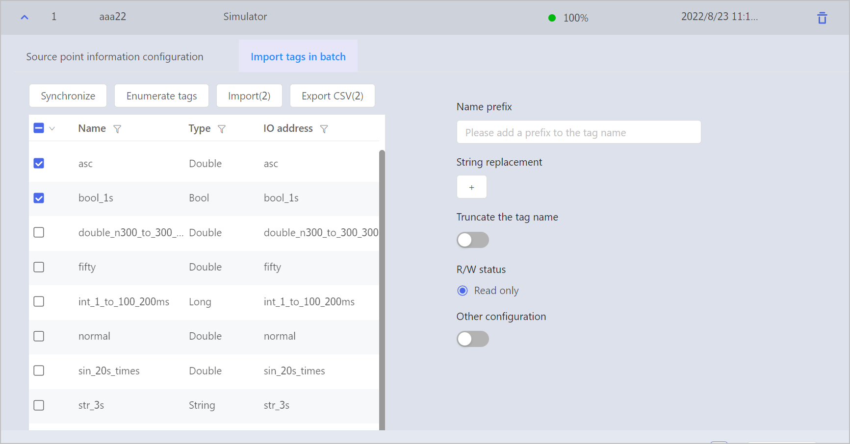
OPC DA driver supports batch import. After you have configured the source, click Import tags in batch to expand information of tag bulk import.
| Parameter | Meaning | Description |
|---|
| (Synchronization) | Incremental Synchronize of tag | Synchronize tag information from OPC Server, in the range of the incremental part. Time is re;atively shorter, and the information may not be complete. |
| (Full Synchronization) | Full synchronization of tag | Synchronize tag information in the range of all. This may take longer time to complete. |
| Add Prefix to Name | Add prefix | If the prefix is filled in, the prefix is added to the selected tag when the tag is imported; if not, no prefix is added. |
| String Replacement | Bulk replacement | - The replacement conditions can be deleted and added, and the filter conditions can be increased to a maximum of 4 and a minimum of 1.
- If characters are written in the original character input box, the replacement are performed; if no characters are filled in the original character input box, the no replacement are performed.
|
| Intercept Tag Name | Intercept Tag Name | Intercept a segment of characters as a tag name based on the specified intercept characters (the separator). The interception is done from right to left in reverse order. Example: The original tag is namedabc&qvs&wer, the specified intercept character is set to &, and the intercepted paragraph is set to 0-1 (backward), then the intercepted tag name iswer; intercept paragraph set 1-2 paragraphs (countdown), then the intercepted tag name isqvs. |
| Read & Write Status | Set the read & write status device tag | If supOS is set to read/write, data can be written down to the data source through the collector. If supOS is set to read only, data cannot be written down. |
| Other Configuration | Unfold detailed configuration item. | - |
| Unit Mode | Set unit mode | User-defined: Input unit manually. From OPC server: units are automatically filled with the OPC data source unit field name. |
| Unit | Tag unit | Tag unit should be in accordance with OPC data source. |
| Range Mode | Set range mode | User-defined: Input upper and lower range limit manually. From OPC server: The upper and lower limit of ranges are automatically filled with data corresponding to OPC data source. |
| Range Max | Set range upper limit | Set according to tag requirements. The default value is 100. |
| Range Min | Set range lower limit | Set range mode limit according to tag requirements. The default value is 0. |
| Description Mode | Set description mode | User-defined: Enter description manually. According to OPC server: Description is automatically filled with OPC data source description field. |
| Description | Edit tag description | Edit tag description. |
- Click Synchronize or Fullsync to synchronize information from source and enumerate tags that have been synchronized to the list.
- You can select tag to edit the parameter of the selected tag.
- Choose the tag to be imported, and click Import to Tag.
- The imported tags are displayed on Tag page.
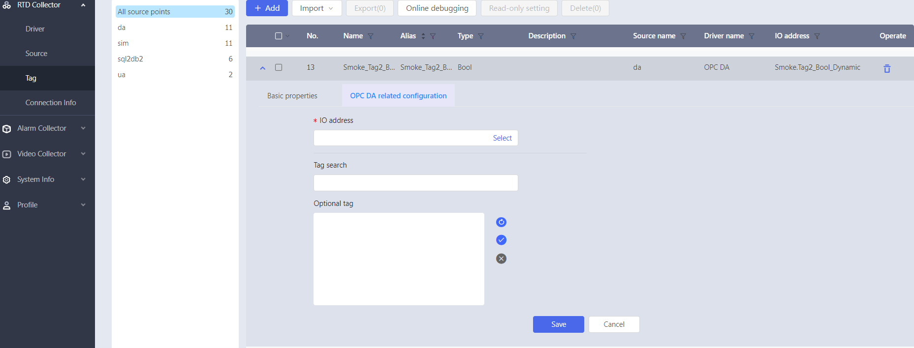
Adding Tag
- Click Add to unfold basic properties of tag.
- After the basic properties are entered, the system automatically adds relevant configuration properties for the settings of connection point between tag and the underlying data.
- Click Select to unfold tag selection information.
- Enter tag information in Tag Search for fuzzy query or click refresh button, and the optional tag will automatically display related items according to the selected source.
- Click blue √ after selecting the corresponding tag, and the system automatically displays I/O address.
- Click Save to complete configuration.
OPC UA
OPC UA driver, mainly used to connect to OPC UA protocol-based
servers for data acquisition.
Adding Source
- Click Add on Source to expand source information.
- Enter source name and description, and select OPC UA for driver name. The system expands the information that needs to be entered for this driver according to the selected driver.
Table 2. OPC UA source point parameter specification| Parameter | Definition | Description |
|---|
| Clock Source | Timestamp used for data updates | |
| Breakage Reconnection | Reconnection mode when OPC Client and OPC Server are disconnected. | Reconnection: Reconnect only when OPC server is disconnected abnormal. Never Reconnect: OPC server does not reconnect after disconnection. Always Reconnect: Reconnects when the OPC server is abnormally disconnected or normally exits. |
| Reconnection Interval | The time interval between two times of reconnection. | Selectable from 30, 60, 120, 300, 600, in seconds. |
| Authorization Settings | OPC UA server authorization | - If OPC UA server is not set username and password, select anonymous to connect.
- If OPC UA server sets user name and password, you need to enter the corresponding user name and password to connect successfully.
|
| Security Settings | - | Encrypted data transmission is supported between the collector and OPC UA server, and the encryption methods are None (no encryption), Sign, Sign & Encrypt. |
| Security Mode | Set OPC UA driver encryption mode | When the security mode is None, there is no need to select a security policy. Other encryption methods can choose 4 security policies: Basic256, Basic128Rsa15, Basic256Sha256, and Aes128Sha256RsaOaep. |
| Security Strategy | Active data reading settings | When enabled, the data is read actively. And the device will periodically read all successfully subscribed tag synchronously. |
| Certificate File der Path | OPC server information | Click Configuration to unfold the information that needs to be entered for the OPC server. After the information is entered, the system automatically generates the OPC server information in the format of OPC Service Address/OPC DA Service". The round light on the right side of the currently connected OPC server is green. |
| Private Key File pem Path | IP address of OPC server | - |
- Enter the IP address of the OPC server you need to connect to, for example: 10.13.156.21.
- Select the breakage reconnection mode, and the default is Always Reconnect
- Select a reconnection interval of 30s.
- Select Local Time as the clock source.
- Select the authorization mode according to the OPC UA server settings.
- Set the data encryption transmission method between the collector and OPC UA server.
- Click Save.
Importing Tag
OPC UA driver supports batch import of tag. After you have configured the source information, go to Import tags in batch tab to expand tag batch import information.
| Parameter | Meaning | Description |
| (Synchronization) | Synchronize tag | Synchronize tag information from OPC Server, in the range of all |
| (Enumerate tag) | Enumerate current tag | Display all tag information of OPC DA data source |
| String Replacement | Bulk replacement | - The replacement conditions can be deleted and added, and the filter conditions can be increased to a maximum of 4 and a minimum of 1.
- If characters are written in the original character input box, the replacement will be performed; if no characters are filled in the original character input box, the no replacement will be performed
|
| Truncate the Tag Name | Truncate Tag Name | Intercept a segment of characters as a tag name based on the specified intercept characters as a separator. The interception is done from right to left in reverse order. Example: The original tag is namedabc&qvs&wer, the specified intercept character is set to &, and the intercepted paragraph is set to 0-1 (backward), then the intercepted tag name iswer; If intercept paragraph is set to 1-2 paragraphs (countdown), then the intercepted tag name is qvs. |
| Read & Write Statua | Set the read & write state equipment tag | If supOS is set to read/write, data can be written down to the data source through the collector. If supOS is set to read only, data cannot be written down. |
| Other Configuration | Unfold detailed configuration page | - |
| Grouping | Tag grouping | By default, the software establishes 128 groups from 0 to 127, you can manage the tag in groups according to tag classification. |
| Unit Mode | Set unit mode | User-defined: Input unit manually. From OPC server: units are automatically filled with the OPC data source unit field name. |
| Unit | Tag unit | Tag unit should be in accordance with OPC data source. |
| Range Mode | Set range mode | User-defined: Input upper and lower range limit manually. From OPC server: The upper and lower limit of range are automatically filled with data corresponding to OPC data source. |
| Range Max | Set range upper limit | Set according to tag requirements. The default value is 100. |
| Range Min | Set range lower limit | Set according to tag requirements. The default value is 0. |
| Description Mode | Set description mode | Customize: Input description manually. From OPC server: Description is automatically filled with OPC data source description field. |
| Description | Edit tag description | Edit tag description information. |
- Click Enumerate Tags, and the system will systematically enumerate tag information corresponding to the source point. If a new tag is added to the source, perform Synchronization before tag enumeration.
- You can select tag to edit the parameter information of the selected tag.
- Choose the tag to be imported, and click Import.
- The imported tags are displayed on tag page.
Adding Tag
- Click Add to unfold basic properties of tag.
- After the basic property content is input, the system automatically adds the relevant configuration properties for the connection point between tag and the underlying data.
- Click Select to unfold tag selection information.
- Enter tag information in Tag Search for fuzzy query or click the refresh button, and the optional tag will automatically display related items according to the selected source.
- Click blue √ button after selecting the corresponding tag, and the system automatically displays the I/O address.
- Click Save to complete configuration.
Modbus RTU
Modbus RTU protocol driver. The caller can implement the access
to the standard Modbus RTU system.
Adding Source
- Click Add on Source to expand source information.
- Enter source name and description, and select Modbus RTU for driver name. The system expands the information that needs to be entered for this driver according to the selected driver.
- Click Channel to add channels and configure channel parameters. Parameter description is as follows.
Table 3.
Channel parameter specification
| Parameter | Meaning | Description |
|---|
| Channel | Channel | - |
| *Name | - | - |
| Description | - | - |
| *Serial Port | Device number | Device ID is unique, and must be the same with original device ID. |
| *Baud Rate | Baud rate of channel | The settings must be consistent with the corresponding parameters of serial port of the other party. |
| Stop Bit | Time between transmission of each character, measured in bits per second. | The optional parameters are 1, 1.5 and 2, and the default is 1. The settings must be consistent with the parameters corresponding to PLC. |
| Parity | Type of error checking for the port. | Optional parameters include the following:- None, indicating that no parity bit is added to data bits sent from this port.
- Odd, indicating that if the number of 1's in the data bits is to be odd. The parity bit should be added.
- Even, indicating that if the number of 1's in the data bits is to be even. The parity bit should be set to 1.
- Mark, meaning adding parity bit. (always set to 0).
- Space, meaning adding parity bit (always set to 1). The settings must be consistent with the parameters corresponding to the serial port of the other party.
|
| Stop Bit | Time between transmission of each character, measured in bits per second. | The optional parameters are 1and 2. The settings must be consistent with the parameters corresponding to the serial port of the other party. |
| *Time-out Time | The maximum waiting time between the command sent by the master and response | |
- Select a channel, click Device to add a device and configure device parameters. The parameters are shown in the following table.
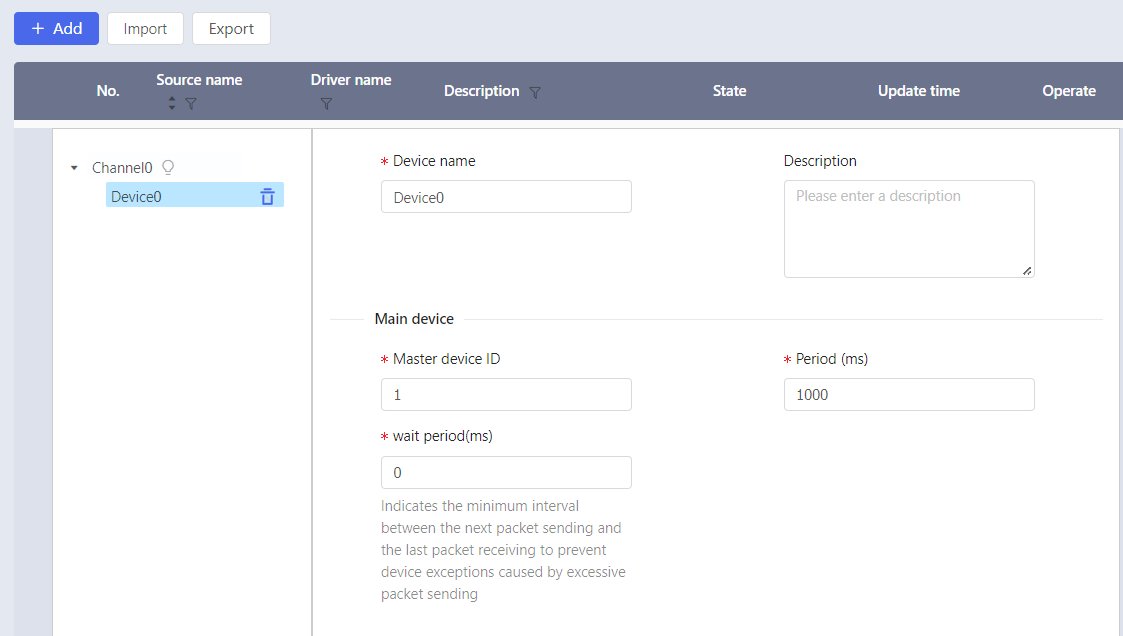
Table 4.
Device parameter specification
| Parameter | Meaning | Description |
|---|
| *Device Name | Device name | Device under the same channel cannot be repeated. Device name contain Chinese characters. |
| Description | - | - |
| *Mater Device ID | Device ID | Device ID is unique, and must be the same with original device ID. |
| *Period | Time interval of two packets | Data are updated every other time interval. Unit: ms. The default value is 1000. |
Importing Tag
MODBUS RTU driver supports batch import of tag. After you have finished configuring the source information, please perform the following steps.
- Go to Import Tags in Batch tab, and unfold batch import tag information.
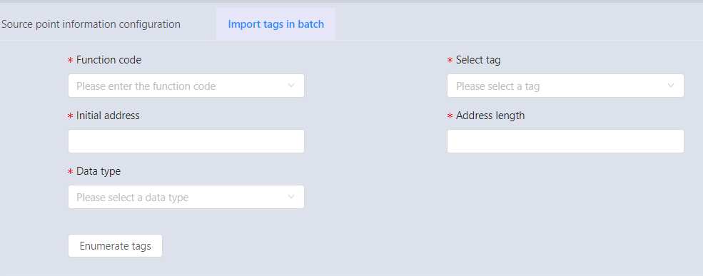
Table 5. Parameter specification| Parameter | Meaning | Description |
|---|
| *Function Node | - | 01 COIL: 1 address type, coil type, 1 bit,
read/write (1 command to read, 5, 15 command
to write) 02 DISCRETES INPUT: 2 address type, discrete
amount, 1 bit, read only (2 command read) 03 HOLDING REGISTER: 3 address type, holding
register, 2 bytes, read/write (3 command to
read, 6, 16 command to write) 04 INPUT REGISTER: 4 address type, input
register, 2 bytes, read-only (4 command to
read) |
| *Select Tag | - | Select the source tag created, e.g. Device0. |
| *Initial Address | Start address of data block | - |
| *Address Length | The difference between the end address and the start address. | COIL, DISCRETES INPUT type address with a maximum length of 2000, the minimum is 1; INPUT REGISTER, HOLDING REGISTER type address with a maximum length of 125, the minimum length of 1. |
| Data Type | Data type | Data type of data source, as well as
forward/reverse order, byte swapping, etc. - string: selection of encoding and string length.
- bool: bit setting
- short/unshort: AB/BA
- long/unlong/float: ABCD/CDBA/BADC/DCBA
- double: asc/decs
- byte/char: A/B
|
- Click Enumerate Tags. After you have selected the tags to be imported, click Import.
For operation on tag name (prefix adding, string swapping, intercepting, etc), please refer to Importing Tag.
Adding Tag
- Click Add to unfold basic properties of tag.
- After the basic property content is entered, the system automatically adds the relevant configuration properties for the connection point between tag and the underlying data.
- Select tag, for example, Device0.
- Enter address. (range: 0 - 65535).
- Select function code and data type. (Please refer to Modbus RTU Importing Tag for details.)
- Click Save to complete configuration.
Modbus TCP
Modbus TCP protocol driver. The caller can implement the access
to the standard Modbus TCP system.
Adding Source
- Click Add on Source to expand source information configuration.
- Enter source name and description, and select Modbus TCP for the driver name. The system expands the information that needs to be entered for this driver according to the selected driver.
- Click Device to add devices and configure device parameters. Parameter description is as follows.
| Parameter | Meaning | Description |
|---|
| Device | Device | - |
| *Name | Device name | Device name under the same channel is not allowed to be repeated, and several devices can be hung under one channel. The name cannot use Chinese and Chinese characters |
| Description | Device description | The light bulb to the right of the currently connected device is on. |
| *IP | Device IP address | - |
| *Port | - | - |
| *Port ID | Device TPC port number | - |
| *Device ID | Device slave ID | Device ID is unique. |
| *Time-out Time | The maximum waiting time between the command sent by the master and response | The default value is 1000. |
| *Period | Time interval between two packets | Get updated data every cycle in ms, default value is 1000. |
| Max Pending Packets | - | maximum number of times for waiting for packets to be sent. (The default time is 5.) |
| Redundancy Configuration | Whether to start redundant OPC Server | The collector supports reading data from the
redundant OPC Server. The collector can communicate with the
redundant OPC Server. When one OPC Server
fails, it automatically switches to the
non-failed OPC Server to continue
communication. When both the master and slave
OPC Server fail, communication with the OPC
Server is interrupted, and when one of them
returns to normal, communication is
automatically restored. The items to be configured are the same as the
master OPC Server. |
- Click Save to complete configuration.
Importing Tag
MODBUS TPC driver supports batch import of tag. After you have finished configuring the source information, please follow the following steps.
- Go to Import Tags in Batch tab, and unfold information for batch import.
Table 6. Parameter specification| Parameter | Meaning | Description |
|---|
| *Function Node | Function type | 01 COIL: 1 address type, coil type, 1 bit,
read/write (1 command to read, 5, 15 command
to write) 02 DISCRETES INPUT: 2 address type, discrete
amount, 1 bit, read only (2 command read) 03 HOLDING REGISTER: 3 address type, holding
register, 2 bytes, read/write (3 command to
read, 6, 16 command to write) 04 INPUT REGISTER: 4 address type, input
register, 2 bytes, read-only (4 command to
read) |
| *Select Tag | - | Select source tag that has been created, e.g. Device0 |
| *Initial Address | Start address of data block | - |
| *Address Length | The difference between the end address and the start address. | COIL, DISCRETES INPUT type address with a maximum length of 2000, the minimum is 1; INPUT REGISTER, HOLDING REGISTER type address with a maximum length of 125, the minimum length of 1. |
| Data Type | Data type | Data type of data source, as well as
forward/reverse order, byte swapping, etc. - string: selection of encoding and string length.
- bool: bit setting
- short/unshort: AB/BA
- long/unlong/float: ABCD/CDBA/BADC/DCBA
- double: asc/decs
- byte/char: A/B
|
- Click Enumerate Tags. After you have selected the tags to be imported, click Import to import tags.
please refer to Importing Tag for detailed operations on tag name (e.g. prefix adding, string swapping and intercepting).
Adding Tag
- Click Add to unfold basic properties of tag.
- After the basic property content is input, the system automatically adds the relevant configuration properties for the connection point between tag and the underlying data.
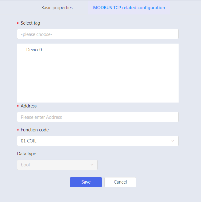
- Select tag, for example, Device0.
- Enter address, ranging from 0 to 65535.
- Select function code and data type. (Refer to Modbus RTU Importing Tag for details.)
- Click Save to complete configuration.
DDE
DDE is a dynamic data exchange (DDE) system. DDE uses a shared memory to exchange data between two applications.
Adding Source
- Click Add on Source to expand source information.
- Enter source name and description, and select DEE for driver name. The system expands the information that needs to be entered for this driver according to the selected driver.
| Parameter | Meaning | Description |
|---|
| *Application Name | DEE server name | Usually, the name of the application is used
as the application name, such as EXCEL. The application needs to run on the same
computer as the collector. |
| *Theme | Data set name of DDE server | File name or worksheet name of the data, such as D:\\test.xlsx. The subject cannot contain Chinese. |
| Collect Interval (ms) | Data acquisition cycle | Data acquisition cycle settings (Unit: ms, default value: 1000) |
- Click Save to complete configuration.
Adding Tag
- Click Add to unfold basic properties of tag.
- After the basic property content is entered the system automatically adds the relevant configuration properties for the connection point between tag and the underlying data. Then set input and output address. For example, R2C4 indicates the cell in the second row and fourth column of a Excel file.
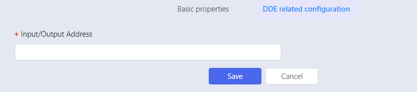
- Click Save to complete configuration.
BACnet TCP/IP
BACnet driver is used for intelligent building communication.
Find all BACnet servers in the same network segment as the IP
address of the collector server by configuring the source. A
collector can only create one valid BACnet source.
Adding Source
- Click Add on Source to expand source information configuration.
- Enter source name and description, and select BACnet for the driver. The system expands the information that needs to be entered for this driver according to the selected driver.
Table 8. BACnet source parameter specification| Parameter | Specification |
|---|
| Virtual Link Layer | Select BACnet IP by default to connect via IP |
| *IP Address | Fill in the IP address of the collector software server (local IP), IP address and subnet mask to determine the BACnet device broadcast segment. |
| *Subnet Mask | Fill in the subnet mask of the collector software server |
| *Port | The default is 47808 |
| *Collect Interval | Set the data collection period in milliseconds (The default is 1000 milliseconds). |
- Click Save to complete configuration.
Since the BACnet driver also acts as a server and the default port is 47808, a collector software can only create one BACnet source.
Importing Tag
BACnet driver supports batch import. After you have configured source information, click into the Import tags in batch tab to expand tag batch import information.
- Add prefix to name: If the prefix is filled in, the prefix is added for the selected tag when importing tags, otherwise prefix will not be added.
- ClickEnumerate Tags. The system will automatically enumerate all BACnet servers in the same IP segment as the collector software.
- Click Import All to import tags.
Adding Tag
- Click Add to unfold basic properties of tag.
- After the basic property content is input, the system automatically adds the relevant configuration properties for the connection point between tag and the underlying data.
- Click Select to unfold tag selection information.
- Enter tag information in Tag Search for fuzzy query or click the refresh button, and the optional tag will automatically display related items according to the selected source.
- Click blue √ button after selecting the corresponding tag, and the system automatically displays the I/O address.
- Click Save to complete configuration.
National Standard
HJ212 2017
Environment HJ212-2017 standard protocol, mainly used to connect the data acquisition instrument ① that adopts the data transmission standard of pollutant online monitoring
(monitoring) system.
Note ① Data Acquisition Devices: Data acquisition and transmission devices that collect data from various types of monitoring devices. These devices store, transmit and communicate with the host computer micro-controller,
industrial control machine, embedded computer, programmable automation controller (Programmable Automation Controller,
PAC) or programmable controller (PLC), etc., and are referred to as Digital acquisition instrument.
Adding Source
- Click Add on Source.
- Enter source name and description, and select HJ212 2017 for the driver. The system expands the information that needs to be entered for this driver according to the selected driver.
Table 9. Device parameter specification| Parameter | Description |
|---|
| Port | Service port |
- Click Device to add devices and configure device parameters. Parameter description is as follows.
| Parameter | Meaning | Description |
|---|
| *Unique Identification (MN) | The unique identification (MN) of the digital mining instrument device, consistent with the site identification | - |
| *Name | Device name | Name is automatically generated. Default value is suggested. |
| *Password | Field machine access password | - |
| *Description | Description of the device, so that you can easily remember the characteristics of the device | - |
- Click Save to complete configuration.
Adding Tag
- Click Add to unfold basic properties of tag.
- Enter basic properties, and select HJ 212 2017 for driver name. The system will automatically configure attributes.
| Parameter | Specification |
|---|
| *Device Unique Identification | The unique identification (MN) of the digital mining instrument device, consistent with the site identification. |
| *System Coding | Select system code. The system code is divided into four
categories, each of which indicates a system
type. - 10~29 indicate environmental quality categories.
- 30~49 denote environmental pollution source categories.
- 50~69 indicates the working condition category.
- 91~99 indicates the system interaction category
|
| Command Encoding | Select the command code. There are four
categories of command codes. - 1000~1999 indicate initialization command and parameter command codes.
- 2000~2999 indicates data command codes.
- 3000~3999 indicates control command codes.
- 9000~9999 indicates interactive command codes
|
| Query Interval | Time interval for the collector to actively check the data. |
| *Target Field | Field name of data area. |
| Target Field Parameter | The value of xxxxxxx or xxx in the target field. |
| Custom Data Fields | User-defined CP field value (without
&&), some data need to be actively
queried in time (It cannot be subscribed),
this field as CP parameters passes in when
query is requested. For example: the command
code 3020 (to extract the information of the
field machine) can be set to
CP=&&PolId=w01018;
InfoId=i12001&& in the data area when
the request is initiated. The field is valid when the current command
code is
1011,1061,1063,3015,3017,3018,3019,3020. |
- Click Save to complete the configuration.
See HJ212-2017 Data Transmission Standards for Pollutant Online Monitoring Systems for detailed HJ212 2017 standard protocol information.
HJ212 2005
Adding Source
- Click Add on Source to expand source information.
- Enter source name and description, and select HJ212 2005 for the driver. The system expands the information that needs to be entered for this driver according to the selected driver.
Table 12. HJ212 2005 Source Parameter Specification| Parameter | Description |
| Port | Service port |
- Click Device to add devices and configure device parameters. Parameter description is as follows.
| Parameter | Meaning | Description |
|---|
| *Unique Identification (MN) | The unique identification (MN) of the digital mining instrument device, consistent with the site identification | - |
| *Name | Device name | Name is automatically generated. Default value is suggested. |
| *Password | Field machine access password | - |
| *Description | Description of the device, so that you can easily remember the characteristics of the device | - |
- Click Save to complete configuration.
Adding Tag
- Click Add to unfold basic properties of tag.
- Enter basic properties, and select HJ212 2017 for driver name. The system will automatically configure attributes.
| Parameter | Specification |
|---|
| *Device Unique Identification | The unique identification (MN) of the digital mining instrument device, consistent with the site identification. |
| *System Coding (ST) | 21: Surface water monitoring 22: Air quality monitoring 23: Regional environmental noise monitoring 31: Atmospheric environmental pollution
sources32: Surface water environmental pollution
sources 33: Groundwater environmental pollution
sources 34: Marine environmental pollution sources 35: Soil environmental pollution sources 36: Sound environmental pollution sources37: Vibration environmental pollution sources 38: Radioactive environmental pollution
sources41: Electromagnetic environmental pollution
sources 91: System interaction |
| Command Encoding (CN) | 1000: Set timeout time and retransmission
times 1011: Extract field machine time
1012: Set field machine time 1061: Extract real-time data interval 1062: Set real-time data interval 1072: Set field machine password
2011: Get pollutant real-time data 2021: Get equipment operation status data
2031: Get pollutant daily history data2041: Get equipment operation Time daily
historical data 2051: Get pollutant minute data 2061: Get pollutant hourly data3011: Zero calibration, full scale calibration 3012: Instant sampling command
3013: Equipment operation command 3014: Set equipment sampling time period |
| Query Interval | Time interval for the collector to actively check the data. |
| *Target Field | Field name of data area. |
| Target Field Parameter | The value of xxx in the target field (see HJ/T 212-2005 standard document, appendix B: Coding Schedule of Common Pollutants). |
| Custom Data Fields | Used when distributing data. |
- Click Save to complete configuration.
Note:
Please refer to Standard for Data Communication of Pollution Emission Auto Monitoring System for more information of HJ212 2005 standard protocol information.
DLT 645
DLT645 driver, DL/T645-2007 protocol, for connecting
multifunctional power meters.
Adding Source
- Click Add on Source to expand source information.
- Enter source name and description, and select DLT645 for the driver. The system expands the information that needs to be entered for this driver according to the selected driver.
| Parameter | Meaning | Definition |
|---|
| *Port | Communication port | - |
| *Baud Rate | Baud rate for channel operation | You can set 110, 300, 600, 1200, 2400, 4800,
9600, 14400, 19200, 38400, 56000, 57600,
115200, 921600. The settings must be consistent with the
corresponding parameters on the DLT645 server. |
| *Parity | Error checking type of port. | Optional parameters include the following: - Odd parity, which indicates that the parity bit should be set to 1 if the number of 1 in the data bits is to be odd.
Even parity, indicating that if the
number of 1 in the data bits is to be
even, the parity bit should be set to 2. The setting must be consistent with the
corresponding parameters of the DLT645
server.
|
- Click Device to add devices and configure device parameters. Parameter description is as follows.
| Parameter | Meaning | Specification |
|---|
| Device | Device | - |
| *Device Name | Device name | Name is automatically generated. Default value is suggested. Name should be a combination of alphanumeric underscores. Device name is unique under the same source. |
| *Device Address | Production address of power meter | Device address under the same source is unique. |
| Description | Description of device | - |
- Click Save to complete configuration.
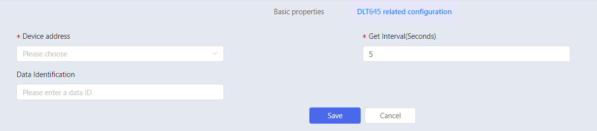
Adding Tag
- Click Add to unfold basic properties of tag.
- After the basic property content is input, the system automatically adds the relevant configuration properties for the connection point between tag and the underlying data.
| Parameter | Meaning | Description |
|---|
| *Device Address | Production address of ammeters. | Form: Device name /Ammeter address |
| *Get Interval | Tine interval for obtaining power meter data. | Set the acquisition frequency in seconds. (Default is 5s.) |
| Data Identification | Data identification code identifies different data items with 4 bytes. | See DL/T645-2007communication protocol for details. |
- Click Save to complete configuration.
DLT698
DLT698 driver, DL/T698-2007 protocol, for connecting multifunctional power meters.
Adding Source
- Click Add on Source to expand source information.
- Enter source name and description, and select DLT698 for the driver. The system expands the information that needs to be entered for this driver according to the selected driver.
| Parameter | Meaning | Description |
|---|
| *Port | Communication port | Name of port connected with DLT698 device. For example, COM1. Click Test to test port connection. |
| *Baud Rate | Baud rate for channel operation | The settings must be consistent with the those
corresponding to DLT698 device. |
| *Parity | Error checking type of port. | Optional parameters include the following: - Odd parity, which indicates that the parity bit should be set to 1 if the number of 1 in the data bits is to be odd.
Even parity, indicating that if the
number of 1 in the data bits is to be
even, the parity bit should be set to 2. The setting must be consistent with the
corresponding parameters of the DLT698
server.
|
| *Data Bit | Valid data bit number during data transmission | Selectable number: 5, 6, 7, 8. Parameters must be consistent with those corresponding to DLT698. |
| *Client Address | - | Form: two hexadecimal characters. For example, A2. |
| *Stop Bit | Stop bit marks the end of a data frame, providing the | Selectable number: 1, 2 (1 by default). Settings should be consistent with corresponding parameters of DLT 698 device. |
- Click Device to add devices and configure device parameters. Parameter description is as follows.
| Parameter | Meaning | Description |
|---|
| *Device Name | Device name | Self-defined. Default name is suggested. |
| *Device Address | Address of meter | Server Address |
| Description | Description of device | - |
| *Maximum byte number | Maximum length of data packet | 64-1048576. (512 by default). |
- Click Save to complete configuration.
Adding Tag
- Click Add to unfold basic properties of tag.
- After the basic property content is input, the system automatically adds the relevant configuration properties for the connection point between tag and the underlying data.
| Parameter | Meaning | Description |
|---|
| *Device Address | | Format: Device name/Meter address |
| Data Identification | Used to identify different data item. | Please refer to documents of DL/T698-2017 communication protocol for details. |
| *Get Interval | Time interval of acquiring data on electric energy meter | Set the acquisition frequency in seconds, the default is 5s. Note: The actual interval time is related to the external environment and may be greater than the set interval time. |
| *Array Subscript | Arrary index of acquired data | Starting from 0. Set to 0 when it is not array. |
- Click Save to complete configuration.
Relational Database
SQL2DB
SQL to DB driver, mainly used for collecting data from
relational databases.
Adding Source
- Click Add on Source to expand source information.
- Enter source name and description, and select SQL2DB for the driver. The system expands the information that needs to be entered for this driver according to the selected driver.
| Parameter | Description |
|---|
| *Server Address | IP address of relational database server. |
| *Database Name | Database Name |
| *Database Type | This system supports mysql, sql server and oracle. |
| *Communication Port | Communication port between database and collector. |
| *Login Username | Username for logging into database. |
| *Login Password | Password for logging into database. |
| *Table Name | Table name of database that needs to be connected. |
| *Collect Interval (Second) | The database sets the data collection period in seconds, the default is 1 second. |
| Connection Test | Test whether the database connection is successful. |
- Enter the IP address of the relational database server you need to connect to, for example: 10.13.156.21.
- Enter the name of the relational database to be connected, consistent with the database name.
- Select corresponding data base, for example: oracle.
- Enter communication port for database, for example: 1521, consistent with the database communication port.
- Enter login username and password.
- Enter table name that needs to be connected to the database, consistent with the database table name. And the database table fields need to be designed in strict accordance with supOS customization rules, field sorting and data types are listed below.
| Name | Mysql/SQL server | ORACLE | Remark |
|---|
| id | BIGINT | NUMBER | - |
| TagName | VARCHAR | VARCHAR2 | Tag name |
| T | BIGINT | NUMBER | Timestamp (ms) |
| VString | VARCHAR | VARCHAR2 | - |
| Q | INT | NUMBER | Quality code |
| TagType | INT | NUMBER | Tag type, value range 0-5, corresponding to data type String/Integer/Long/Float/Double/Bool |
| VInt | INT | NUMBER | - |
| VLong | BIGINT | NUMBER | - |
| VFloat | FLOAT | FLOAT | - |
| VDouble | DOUBLE | FLOAT | - |
| VBool | TINYINT | NUMBER | - |
| time | DATETIME | DATE | - |
- Set collect interval to one second.
- After the information is entered, click Connection Test.
If you are not sure about database information, please check with the database administrator.
Importing Tag
SQL2DB driver supports batch import. After you have configured source information, go to Import tags in batch tab.
- Click Enumerate Tags. The system will automatically enumerate tag information corresponding to the source.
- Click Import to import tags.
- The imported tags are displayed on Tag page.
Please refer to Appendix A/Table A-2 SQL2DB Type Suggested Correspondence Description for the correspondence between SQL2DB tag type and database field data type.
Adding Tag
- Click Add to unfold basic properties of tag.
- After the basic property content is input, the system automatically adds the relevant configuration properties for the connection point between tag and the underlying data.
- Click Select to unfold tag selection information.
- Enter tag information in Tag Search for fuzzy query or click the refresh button, and the optional tag will automatically display related items according to the selected source.
- Click blue √ button after selecting the corresponding tag, and the system automatically displays the I/O address.
- Click Save to complete configuration.
SQL2DB2
SQL to DB2 driver, mainly used for data acquisition of
relational database. SQL2DB2 is to access data with table
structure to X-Collector. MySQL, Oracle, and SQL Server are
supported. Per data communication, VSTRING is parsed into
corresponding data type according to the type field TAGTYPE.
Adding Source
- Click Add on Source to expand source information.
- Enter source name and description, and select SQL2DB2 for the driver. The system expands the information that needs to be entered for this driver according to the selected driver.
| Parameter | Description |
|---|
| *Database Type | This system supports mysql, sql server and oracle. |
| *Server Address | IP address of relational database server. |
| *Communication Port | Communication port between database and collector. |
| *Database Name | Database Name |
| *Table Name | Table name of database that needs to be connected. |
| *Login Username | Username for logging into database. |
| *Login Password | Password for logging into database. |
| *Collect interval (Second) | The database sets the data collection period in seconds, the default is 1 second. |
| Connection Test | Test whether the database connection is successful. |
- Enter the IP address of the relational database server you need to connect to, for example: 10.13.156.21.
- Enter the name of the relational database to be connected, consistent with the database name.
- Select corresponding data base, for example: oracle.
- Enter communication port for database, for example: 1521, consistent with the database communication port.
- Enter login username and password.
- Enter table name that needs to be connected to the database, consistent with the database table name. And the database table fields need to be designed in strict accordance with supOS customization rules, field sorting and data types are listed below.
| Name | Mysql/SQL server | ORACLE | Remark |
|---|
| id | BIGINT | NUMBER | - |
| TagName | VARCHAR | VARCHAR2 | Tag name |
| T | BIGINT | NUMBER | Timestamp (ms) |
| VString | VARCHAR | VARCHAR2 | - |
| Q | INT | NUMBER | Quality code |
| TagType | INT | NUMBER | Tag type, value range 0-5, corresponding to data type String/Integer/Long/Float/Double/Bool |
| VInt | INT | NUMBER | - |
| VLong | BIGINT | NUMBER | - |
| VFloat | FLOAT | FLOAT | - |
| VDouble | DOUBLE | FLOAT | - |
| VBool | TINYINT | NUMBER | - |
| time | DATETIME | DATE | - |
- Set collect interval to one second.
- After the information is entered, click Connection Test. The configuration is completed if the prompt Connection succeeded pops up.
If you are not sure about database information, please check with the database administrator.
Importing Tag
SQL2DB driver supports batch import. After you have configured the source information, go to Import tags in batch tab.
- Click Synchronize, and the tag information corresponding to this source will be automatically synchronized.
- Click Enumerate Tags. The system will automatically enumerate tag information corresponding to the source.
- Click Import All to import all the tags, or you can select partial tags and click Batch Import.
- The imported tags are displayed on Tag page.
Note: Per correspondence of SQL2DB2 tag type and data type of database, please refer to Appendix A/A-2SQL2DB/SQL2DB2 Data Conversion Rules
ODBC
ODBC driver, used for accessing the database through ODBC.
Adding Source
- Click Add on Source to expand source information.
- Enter source name and description, and select ODBC for the driver. The system expands the information that needs to be entered for this driver according to the selected driver.
| Parameter | Description |
|---|
| *ODBC Data Source | ODBC data source name |
| *Table Name | Table name of the database that needs to be connected. |
| *Collect interval | Set the data collection period in seconds, unit:ms, the default is 1000. |
| *Login Username | Username for logging into database. |
| *Login Password | Password for logging into database. |
- Enter ODBC data source name that needs to be connected.
- Enter the table name of the database that needs to be connected.
- Set collect interval.
- Enter login username and password.
The database table structure should be consistent with the SQL2DB table fields, and ensure that the ODBC connection to the database is successful.
Importing Tag
OBDC driver supports batch import. After you have configured source information, click into the Import tags in batch tab.
- Click Enumerate Tags. The system will automatically enumerate all BACnet servers in the same IP segment as the collector software.
- Click
 to enter query for tag filtering.
 - Click Import to import tags.
- The imported tags are displayed on Tag page.
Adding Tag
- Click Add to unfold basic properties of tag.
- After the basic property content is input, the system automatically adds the relevant configuration properties for the connection point between tag and the underlying data.
- Click Select to unfold tag selection information.
- Enter tag information in Tag Search for fuzzy query or click the refresh button, and the optional tag will automatically display related items according to the selected source.
- Click blue √ button after selecting the corresponding tag, and the system automatically displays the I/O address.
- Click Save to complete configuration.
Power Regulations
IEC101
IEC 101 driver, power system 101 protocol, mainly used to connect IEC101 SLAVE.
Adding Source
- Click Add on Source to expand the source information configuration.
- Enter source name and description, and select IEC 101 for the driver. The system expands the information that needs to be entered for this driver according to the selected driver.
| Parameter | Meaning | Description |
|---|
| *Link Address Length | Link address length | If the link address length is 1, then the link
address range is 1-255. If the link address length is 2, then link
address range is 1-65536. |
| *Link Address | Link address field is slave station address |
| Update Speed | Data update speed | Set update frequency in milliseconds. |
| *Transmission Reason Length | Transmission reason | Byte number of transmission reason (You can choose 1 or 2) |
| Public Address Length | Public address length | Byte number of public address length (You can choose 1 or 2) |
| Info Object Address Length | Address Length of Info Object | Byte number of info object address |
| Master Channel Settings | - | - |
| *Serial Port | Serial port number | Serial port number of the collector server connected to IEC101 server, fill in the number type, e.g. 1 means COM1. |
| *Baud Rate | Baud rate of channel | Baud rate can be set to 110, 150, 300, 600,
1200, 2400, 4800, 9600, 19200, 38400, 57600,
115200. The settings must be consistent with the
corresponding parameters on the IEC101 server. |
| *Parity | Error checking type of port | Optional parameters include the following: None, indicating that no parity bits are added
to the data bits sent from this port. Even, indicating that the parity bit should be
set to 1 if the number of 1's in the data bits
is to be even. Odd, means that if the number of 1's in the
data bits is odd, the parity bit should be
added. Mark, which means that the parity bit is
added, but is always set to 0. Space, which means that parity bits are added
but are always set to 1. The setting must be the same as the
corresponding parameter on the IEC101 service
side. |
| Timeout Time | The maximum waiting time between the command sent by the master and the response | Unit: ms |
| Retry Delay | Delay time | Time interval between packet timeout and the next packet. |
| Number of Retries | Number of times to retry sending the command
after the command response timeout. | The default setting is 3 times |
| Info Type | Single point information setting. | Select the corresponding information type, enter the public address (COA), and the COA corresponds to the Slave configuration. |
| Double point information setting. |
| Normalized value setting. |
Adding Tag
- Click Add to unfold basic properties of tag.
- After the basic property content is input, the system automatically adds the relevant configuration properties for the connection point between tag and the underlying data.
- Select tag and enter block offset i.e. select the location of the data; selecting 0 means to read the data from the first place. ClickSave to complete configuration.
IEC 103
IEC 103 driver, power system 103 protocol, used to connect
IEC103 SLAVE.
Adding Source
- Click Add on Source to expand the source information configuration.
- Enter source name and description, and select IEC 103 for the driver. The system expands the information that needs to be entered for this driver according to the selected driver.
| Parameter | Meaning | Description |
|---|
| *Link Address | Link address field is slave station address | The link address range is 1-255. |
| *COA | Public address of application service data unit | COA corresponds to the Slave configuration, ranging from 0-255. |
| Collect Interval (ms) | Data acquisition interval frequency | Baud rate can be set to 110, 300, 600, 1200,
2400, 4800,9600, 14400, 19200, 38400, 56000,
57600, 115200, 128000, 256000. The settings must be consistent with the
corresponding parameters on the IEC103 server. |
| Master Channel Setting | | |
| *Serial Port | Serial port number | Serial port number of the collector server connected to IEC101 server, fill in the number type, e.g. 1 means COM1 |
| *Baud Rate | Baud rate of channel | Baud rate can be set to 110, 150, 300, 600,
1200, 2400, 4800, 9600, 19200, 38400, 57600,
115200. The settings must be consistent with the
corresponding parameters on the IEC101 server. |
| *Parity | Error checking type of port | Optional parameters include the following: None, indicating that no parity bits are added
to the data bits sent from this port. Even, indicating that the parity bit should be
set to 1 if the number of 1's in the data bits
is to be even. Odd, means that if the number of 1's in the
data bits is odd, the parity bit should be
added. Mark, which means that the parity bit is
added, but is always set to 0. Space, which means that parity bits are added
but are always set to 1. The setting must be the same as the
corresponding parameter on the IEC101 service
side. |
| *Data Bit | Number of data bits used in the transmission and reception of each character | Optional parameters are 5, 6, 7, 8, and the
default selection is 8. The setting must be consistent with the
corresponding parameters of IEC103 server. |
| Timeout Time | The maximum waiting time between the command sent by the master and the response | Default value is 5000ms. |
| *Stop Bit | Transmission time between each character,
measuring by bits/second. | Optional parameters are 1, 1.5, 2, the default
choice is 1. The setting must be the same as the
corresponding parameter on the IEC103 server. |
- Click Save to complete configuration.
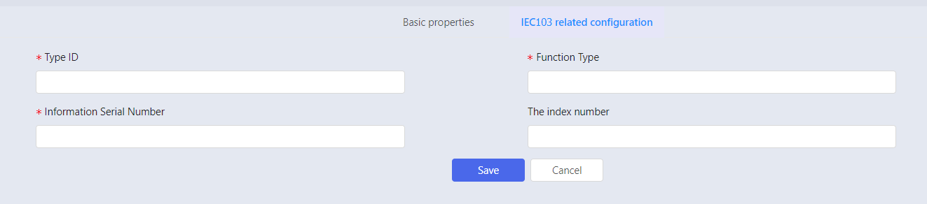
Adding Tag
- Click Add to unfold basic properties of tag.
- After the basic property content is entered, the system automatically adds the relevant configuration properties for the connection point between tag and the underlying data.
| Parameter | Meaning | Specification |
|---|
| *Type Identification | Type identifier (TYPE IDENTIFICATION-TYP) in the data unit identifier of the Application Service Data Units (ASDUs). | <0-255> |
| *Function Type | Function type (FUNCTION TYPE-FUN) in the information body identifier of the Application Service Data Units (ASDUs). | <0-255> |
| *Information Serial Number | Information number (INFORMATION NUMBER-INF) in the information body identifier of the Application Service Data Units (ASDUs). | <0-255> |
| Index Number | Sequence number when a frame of data contains multiple sets of data elements. | <0-127> |
- Click Save to complete configuration.
IEC104
IEC 104 driver, power system 104 protocol, used to connect
IEC104 SLAVE.
Adding Source
- Click Add on Source to expand source information.
- Enter source name and description, and select IEC 104 for the driver. The system expands the information that needs to be entered for this driver according to the selected driver.
| Parameter | Meaning | Description |
|---|
| Collect Interval (ms) | Data collect interval | Set the update interval in milliseconds |
- Click Channel to add channel(s) and set related parameters. Parameter specifications are described as the following table:
| Parameter | Meaning | Description |
|---|
| *Name | Channel name | Channel name is generated automatically. Default name is suggested. |
| *Slave IP | Slave IP | - |
| *Main Port | Port number for device communication | - |
| *Total Summoning Interval (ms) | - | - |
| *Timeout Time (ms) | Timeout Time for channels | Default value is 30000ms. Greyed by default, uneditable |
| *Message Queue Length | Maximum length of the queue for sending commands. | Default is 0,meaning infinite length. Default is grayed and cannot be edited. |
- Click Session under the channel and set session parameter. Parameter specifications are as the following table.
| Parameter | Meaning | Description |
|---|
| Session | Session | - |
| *Name | Session Name | Name under the same session cannot be repeated. |
| *OA | Transmitted master station address. | 0 by default |
| *Timeout Time | Timeout Time for channels | Default value is 30000ms. Greyed by default, uneditable. |
- Click Public Address to add sectors and set sector parameters. Sector parameters are listed in the following table.
| Parameter | Meaning | Description |
|---|
| Sector | Sector | - |
| *Name | Sector name | Name under the same sector cannot be repeated. |
| *COA | Sector offset address | COA must correspond to SLAVE configuration, ranging from 0 to 65533. |
- Click Save to complete configuration.
Adding Tag
- Click Add to unfold basic properties of tag.
- After the basic property content is input, the system automatically adds the relevant configuration properties for the connection point between tag and the underlying data.
- Select tag and enter IOA address (IEC104 tag). ClickSave to complete configuration.
IEC61850
IEC61850 driver, power system 61850 protocol.
Adding Source
- Click Add on Source to expand the source information.
- Enter source name and description, and select IEC 61850 for the driver. The system expands the information that needs to be entered for this driver according to the selected driver.
| Parameter | Meaning | Description |
|---|
| IP Address | IP Address | Localhost by default |
| Port | Port | 102 by default |
Adding Tag
- Click Add to unfold basic properties of tag.
- After the basic property content is input, the system automatically adds the relevant configuration properties for the connection point between tag and the underlying data.
- Select I/O address and function constraint. Click Save to complete configuration. '
| Function Name | Definition |
|---|
| ST | Status information |
| MX | Measurements |
| CO | Control |
| SP | Specification |
| SV | Substitute |
| DC | Description |
| SG | Setting group |
| SE | Editable setting group |
| EX | Extension |
| BR | Buffered Report Control Block |
| RP | Unbuffered report control blocks |
| LG | Log control block |
| GO | GOOSE control block |
| GS | GSSE control block |
| MS | Multicast sample value control block |
| US | Unicast sampled value control block |
CDT
CDT protocol driver, mainly used to acquire grid data and
monitor system to manage remote devices.
Adding Source
- Click Add on Source to expand the source information.
- Enter source name and description, and select CDT for the driver. The system expands the information that needs to be entered for this driver according to the selected driver.
- Click Channel to add channel(s) and set related parameters. Parameter specifications are in the following table:
Table 34. Channel parameter specification| Parameter | Meaning | Description |
|---|
| Channel | Channel | - |
| *Name | Channel name | Channel name is generated automatically. Default value is suggested. |
| Description | Description of channels | - |
| *COM | Serial port number | Serial port number of the collector server that establishes connection with CDT server. |
| *Baud Rate | Baud rate of channel | Baud rate can be set to 110, 150, 300, 600,
1200, 2400, 4800, 9600, 19200, 38400, 57600,
115200. The settings must be consistent with the
corresponding parameters on the IEC101 server. |
| *Parity | Error checking type of port | Optional parameters include the following: None, indicating that no parity bits are added
to the data bits sent from this port. Even, indicating that the parity bit should be
set to 1 if the number of 1's in the data bits
is to be even. Odd, means that if the number of 1's in the
data bits is odd, the parity bit should be
added. Mark, which means that the parity bit is
added, but is always set to 0. Space, which means that parity bits are added
but are always set to 1. The setting must be the same as the
corresponding parameter on the IEC101 service
side. |
| *Data Bit | Number of data bits used in the transmission and reception of each character | Optional parameters are 7 or 8, and the
default selection is 8. The setting must be consistent with the
corresponding parameters of CDT. |
| *Stop Bit | Transmission time between each character,
measuring by bits/second. | Optional parameters are 1, 2, and the default
choice is 1. The setting must be the same as the
corresponding parameter of CDT server. |
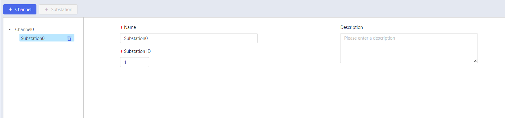
- Click Substation under the channel and configure substation. Parameter specifications are as the follow table.
| Parameter | Meaning | Description |
|---|
| *Name | Substation name | Substation name under the same Channel cannot be repeated. |
| Description | Description of substation | - |
| *Substation ID | Substation ID | The setting must correspond to the parameter of the CDT server, and the setting range is 1~255 |
- Click Save to complete configuration.
Adding Tag
- Click Add to unfold basic properties of tag.
- After the basic property content is input, the system automatically adds the relevant configuration properties for the connection point between tag and the underlying data.
- Select tag (the CDT driver substation to be connected) and function constraint. Select the type to be connected, frame class code, function code and sequence number. You can refer to the corresponding parameters of the CDT server when setting parameters.
- Type:
Selectable parameters include Telemetry,Telemetry,
Electric Energy Pulse and SOE. SOE stands for the
record of sequence of time.
Data type corresponding to remote signalling is
Boolean; The data type corresponding to "telemetry"
and "electric energy pulse" is the numeric type
converted from hexadecimal to decimal; the data type
corresponding to SOE is Boolean, and the return
value is 1 when the event occurs and 0 when the
event does not occur.
- Frame Class Code:
When Type is
Telemetry, the optional parameters are 97, 179 and 194, 97 corresponds to frame A, 179 corresponds to frame C and 194 corresponds to frame B. When
Type isTeleignalling, the default parameter is 244. When Type isElectric Energy Pulse
, the default parameter is 244.
When Type is
SOE, the default parameter is 38. - Function Node: Function node stands for the data corresponding to the row in which it is located. When Type isTelemetry, the optional parameters are 0 to 127. 0 means the data of telemetry 0.
When
Type isTeleignalling, the selectable parameters are 240 to 255, 240 means the data of the first group, each group has 32 data lines; 241 means the data of the second group, and so on. When Type selects
Electric Energy Pulse , the optional parameters are 160 to 223, and 160 means the data of electricity 0. When Type is
SOE, the optional parameters are 128 and 129, which indicates the return results corresponding to 80H and 81H, both of which are currently returned. - Sequence Number:
When Type is
Telemetry, the optional parameters are 0 and 1, indicating the data for the corresponding column.When
Type is Teleignalling, The optional parameters are 0 to 31. 0 means the first line of data of each group; for example, the function code is 241, and the sequence number is 0 corresponding to the first line of data of the second group, i.e., the 32nd line of data (starting from the 0th line). When
Type isElectric Energy Pulse , the optional parameter is 0. When
Type isSOE, the optional parameters are 0 to 4095, corresponding to the object number of the server.
- Click Save to complete configuration.
Intelligent Device
BH 5000 driver, mainly used to connect to BH 5000 protocol-based servers for data acquisition.
Adding Source
Click Add onSource page.
Enter source name and description, and selectBH5000
for the driver. The system expands the information that
needs to be entered for this driver according to the
selected driver.
Table 35. BH5000 source parameter specification| Parameter | Meaning | Specification |
|---|
| *Node | Communication connection node | - |
| Update Rate | Update rate of tag value | Configure update rate, range: 100-5000ms. |
| IP | Server IP Address | - |
| Port | Port number of server | - |
Click Select to expand
the information that needs to be entered for BH5000.
Enter the IP address and port of the BH5000 you want to
connect to, and click
Search. Select the corresponding node ID and clickConfirm, and the node
information will be generated automatically.
Click Save to complete
configuration.
Adding Tag
Click Add to unfold
basic properties of tag.
After the basic property content is input, the system
automatically adds the relevant configuration properties
for the connection point between tag and the underlying
data.
Click Select, and the
node automatically displays related items according to the
selected source.
Select corresponding node, and property textbox will
display properties of selected node.
After you have selected corresponding properties, click
Confirm, and the system automatically generates I/O address. Click Save to complete
configuration.
Simulation Driver
Data source simulator, mostly used for internal test.
FANUC
All PCMIA Series
All PCMIA series are used to connect to the full range of Fanuc PCMIA CNCs via the network port.
Adding Source
- Click Add on Source to expand the source information configuration.
- Enter source name and description, and select All PCMIA Full Series for the driver. The system expands the information that needs to be entered for this driver according to the selected driver name.
Table 36. Source parameter specification of all PCMIA series| Parameter | Meaning | Description |
|---|
| *IP Address | Device IP address | - |
| *Port | Port number | - |
| Timeout Time | Maximum wait time for device connection timeout | Default value is 5000, unit: milliseconds (ms) |
| Collect Interval (ms) | Update cycle of data | Configure the time period of data acquisition. Unit: ms |
Adding Tag
- Click Add to unfold basic properties of tag.
- After you have entered basic properties, the system automatically generates related configuration attributes for the connection point between tag and the underlying data. Select corresponding IO address, and clickSave to complete configuration.
| Number | IO Address | Data Type | Description |
|---|
| 1 | GetCurrentPath | int | Get current channel |
| 2 | GetMaxPath | int | Get maximum path |
| 3 | GetProducts | int | Get products |
| 4 | GetModeInfo | int | Get mode info |
| 5 | GetStateInfo | int | Get state info |
| 6 | GetToolNum | int | Get tool number |
| 7 | GetToolOffsetNum | int | Get tool offset number |
| 8 | GetSFeed | int | Get spindle feed |
| 9 | GetFeedRate | int | Get speed rate |
| 10 | RapidFeed | int | Rapid feed |
| 11 | GetSetSpSpeed | int | Get setting spindle speed |
| 12 | GetActSpSpeed | int | Get actual spindle speed |
| 13 | GetSetFeedSpeed | int | Get set feed speed |
| 14 | GetActFeedSpeed | int | Get actual feed speed |
| 15 | GetSpLoad | int | Get spindle load |
| 16 | GetCNCType | string | Get CNCT type |
| 17 | GetAlarmMsg | string | Get alarm message |
| 18 | GetCurrent | string | Get current |
| 19 | GetKeepAliveTime | string | Keep alive time |
| 20 | GetRunTime | string | Run time |
| 21 | GetCutTime | string | Cut time |
| 22 | GetCycTime | string | Cycle time |
| 23 | GetSMotorTemp | string | Spindle motor temperature |
| 24 | GetServoMotorTemp | string | Servo motor temperature |
| 25 | GetProcessStatus | string | Process satus |
| 26 | GetAbsPosX | double | Absolute position X |
| 27 | GetAbsPosY | double | Absolute position Y |
| 28 | GetAbsPosZ | double | Absolute position Z |
| 29 | GetMacPosX | double | Machinery position X |
| 30 | GetMacPosY | double | Machinery position Y |
| 31 | GetMacPosZ | double | Machinery position Z |
| 32 | GetRelPosX | double | Relative position X |
| 33 | GetRelPosY | double | Relative position Y |
| 34 | GetRelPosZ | double | Relative position Z |
| 35 | GetRemPosX | double | Remaining position X |
| 36 | GetRemPosY | double | Remaining position Y |
| 37 | GetRemPosZ | double | Remaining position Z |
R Series
Connect Fanuc R series robots via network port.
Adding Source
- Click Add on Source to expand the source information configuration.
- Enter source name and description, and select R Series for the driver. The system expands the information that needs to be entered for this driver according to the selected driver.
| Parameter | Meaning | Description |
|---|
| *IP Address | IP Address of device | - |
| *Port | Port number | 60008 by default |
| Collect Interval (ms) | Update cycle of data | Configure the time period of data acquisition, unit: ms |
Adding Tag
- Click Add to unfold basic properties of tag.
- After the basic property content is entered, the system automatically adds the relevant configuration properties for the connection point between tag and the underlying data.
| Parameter | Meaning | Specification |
|---|
| *IO Address | IO address type | D (Data register) AI (input register) AQ (output register) I (Input Relay) Q (output relay) M (Intermediate Relay) |
| *Data Type | Data type of tag | IO address type is D/AI/AQ, and the data type
can choose a type other than bool. Bool cannot
be chosen. IO address type is I/Q/M, and data type can
only be bool. |
| *Address Offset | Address offset | Select the offset value, i.e., select the position of the data. Select 0 means to read the data from the first position. |
| *String Length | String length | Optional string length when string is selected for data format only. |
- Click Save to complete configuration.
Mitsubishi
Mitsubishi CNC
Connect Mitsubishi M700 series CNC (including M700/M700V,
M70/M70V, E70), M800 series CNC (including M800, M800V), and C70
series CNC via TCP/IP protocol.
Adding Source
- Click Add on Source to expand the source information configuration.
- Enter source name and description, and select Mitsubishi CNC for the driver. The system expands the information that needs to be entered for this driver according to the selected driver.
| Parameter | Meaning | Description |
|---|
| *IP Address | IP address of device | - |
| *Port | Port number | 683 by default |
| Timeout Time | Maximum wait time of device connection timeout. | 5000 by default. Unit: ms. |
| Collect Interval (ms) | Data acquisition cycle | Configure the time period of data acquisition. Unit: ms. |
Adding Tag
- Click Add to unfold basic properties of tag.
- After the basic properties are entered, the system automatically adds the relevant configuration properties for the connection point between tag and the underlying data. Select corresponding acquisition point. ClickSave to complete configuration.
| Number | Acquisition Point | Data Type | List View |
|---|
| 1 | Number of current process item | long long | GET_PRODUCT_COUNT_MSG |
| 2 | Current axis number | long long | GET_AXIS |
| 3 | Keep alive time | long long | GET_KEEP_ALIVE_TIME |
| 4 | Current sequence number | long long | GET_SEQUENCE_NUM |
| 5 | Current tool number | long long | GET_TOOL_NO |
| 6 | Actual spindle speed | long long | GET_SPINDLE_ACTUAL_SPEED |
| 7 | Set spindle speed | long long | GET_SPINDLE_SET_SPEED |
| 8 | Spindlr load | long long | GET_SPINDLE_LOAD |
| 9 | Run time | long long | GET_RUN_TIME |
| 10 | System date | long long | GET_SYSTEM_DATE |
| 11 | System time | long long | GET_SYYTEM_TIME |
| 12 | Cycle time | long long | GET_CYCLE_TIME |
| 13 | Start time | long long | GET_START_TIME |
| 14 | Servo axis X load | long long | GET_SERVO_LOAD_X |
| 15 | Servo axis Y load | long long | GET_SERVO_LOAD_Y |
| 16 | Servo axis Z load | long long | GET_SERVO_LOAD_Z |
| 17 | Current program block | string | GET_PROGRAM_BLOCK |
| 18 | CNC model | string | GET_VERSION |
| 19 | Current program name | string | GET_PROGRAM_NO |
| 20 | Alarm message | string | GET_ALARM_MSG |
| 21 | Feed set speed | double | GET_FEED_SET_SPEED |
| 22 | Feed actual speed | double | GET_FEED_ACTUAL_SPEED |
| 23 | Axis X machine position | double | GET_MACHINE_POSTION_X |
| 24 | Axis Y machine position | double | GET_MACHINE_POSTION_Y |
| 25 | Axis Z machine position | double | GET_MACHINE_POSTION_Z |
| 26 | Axis A machine position | double | GET_MACHINE_POSTION_A |
| 27 | Axis X work position | double | GET_WORK_POSITION_X |
| 28 | Axis Y work position | double | GET_WORK_POSITION_Y |
| 29 | Axis Z work position | double | GET_WORK_POSITION_Z |
| 30 | Axis A work position | double | GET_WORK_POSITION_A |
| 31 | Axis X current position | double | GET_CURRENT_POSITION_X |
| 32 | Axis Y current position | double | GET_CURRENT_POSITION_Y |
| 33 | Axis Z current position | double | GET_CURRENT_POSITION_Z |
| 34 | Axis A current position | double | GET_CURRENT_POSITION_A |
| 35 | Axis X distance position | double | GET_DISTANCE_POSITION_X |
| 36 | Axis X distance position | double | GET_DISTANCE_POSITION_Y |
| 37 | Axis X distance position | double | GET_DISTANCE_POSITION_Z |
| 38 | Axis X distance position | double | GET_DISTANCE_POSITION_A |
| 39 | Run status | string | GET_RUN_STATUS_ARR |
| 40 | Read macro variable | According to the actual macro variable | MACRO_VARIABLE |
A_1E_ASCII/A_1E_Binary
A_1E_ASCII: Connects to Mitsubishi PLC via MC Qna1E ASCII protocol.
A_1E_Binary: Connects to Mitsubishi PLC via MC Qna1E Binary protocol.
Adding Source
- Click Add on Source to expand source information configuration.
- Enter source name and description, and select Mitsubishi A_1E_ASCII/A_1E_Binary for the driver. The system expands the information that needs to be entered for this driver according to the selected driver name.
| Parameter | Meaning | Description |
|---|
| *IP Address | Device IP address | - |
| *Port | Port number | 6000 by default |
Adding Tag
- Click Add to unfold basic properties of tag.
- After the basic property content is entered, the system automatically adds the relevant configuration properties for the connection point between tag and the underlying data.
| Parameter | Meaning | Description |
|---|
| *Register Type | Register type | X (input relay) Y (output relay) M (internal relay) L (latching relay) F (Alarm) V (Edge Relay) B (Link Relay) S (Step Relay) D (Data Register) W (Link register) R (file register) |
| *Data Type | Data type of tag | - |
| *Address Display Base | System of the display of address | Octal, decimal, hexadecimal can be selected. |
| *Address Number | Address number | Please enter address number. |
| Bit Offset | Bit offset | Bit offset can only be selected when data type is bool, ranging from 0-7. Selecting 0 means to read from the first bit. |
| String Length | String length | String Length can only be selected when the data type is string. |
- Click Save to complete configuration.
Connect Mitsubishi PLC via Qna 3C protocol.
Adding Source
- Click Add on Source to expand the source information configuration.
- Enter source name and description, and select Mitsubishi A_3C_Format for the driver. The system expands the information that needs to be entered for this driver according to the selected driver.
| Parameter | Meaning | Description |
|---|
| Station Number | PLC station number | PLC address, 0 by default |
| Master Channel Settings | - | - |
| Serial Port | Serial port number | Serial port number of the collector server that establishes connection with the PLC. |
| *Baud Rate | Baud rate of channel | Baud rate can be set to 110, 300, 600, 1200,
2400, 4800, 9600, 14400, 19200, 38400, 56000,
57600, 115200, 128000, 256000. The settings must be consistent with the
corresponding parameters of IEC101 server. |
| Data Bit | Data bit used for transmitting and receiving each character. | The optional parameter is 7 or 8, and the default is 8. The settings must be consistent with the
parameter corresponding to PLC server. |
| Stop Bit | Time between transmission of each character, measured in bits per second. | The optional parameters are 1, 1.5 and 2, and the default is 1. The settings must be consistent with the parameters corresponding to PLC. |
| Parity | Type of error checking for the port. | Optional parameters include the following: |
Adding Tag
For details, see Adding Tag.
A_3C_TCP
Connect to Mitsubishi PLC via Qna 3C Over TCP protocol.
Adding Source
- Click Add on Source to expand the source information configuration.
- Enter source name and description, and select Mitsubishi A_3C_TCP for the driver. The system expands the information that needs to be entered for this driver according to the selected driver.
| Parameter | Meaning | Description |
|---|
| *IP Address | Device IP address | - |
| *Port | Port number | 2000 by default |
| *Station Number | PLC station number | PLC address, 0 by default. |
Adding Tag
For details, seeAdding Tag
.
Fx_Links_485
Connect Mitsubishi PLC through Fx computer chain protocol.
Adding Source
- Click Add on Source to expand source information configuration.
- Enter source name and description, and select Mitsubishi Fx_Links_485 for the driver. The system expands the information that needs to be entered for this driver according to the selected driver.
| Parameter | Meaning | Specification |
|---|
| Station Number | PLC station number. | PLC address, 0 by default. |
| Timeout Time | Maximum wait time of device connection timeout. | 0 by default. Unit: ms. |
| Parity | Device supports checksum varification. | You can select Yes or No. |
| Master Channel Settings | - | - |
| Serial Port | Serial port number | Serial port number of the collector server that establishes connection with the PLC. |
| *Baud Rate | Baud rate of channel | Baud rate can be set to 110, 300, 600, 1200,
2400, 4800, 9600, 14400, 19200, 38400, 56000,
57600, 115200, 128000, 256000. The settings must be consistent with the
corresponding parameters on the IEC101 server. |
| Data Bit | Data bit used for transmitting and receiving each character. | The optional parameter is 7 or 8, and the default selection is 8 The setting must be consistent with the parameter corresponding to the PLC server. |
| Stop Bit | Time between transmission of each character, measured in bits per second. | The optional parameters are 1, 1.5 and 2, and the default selection is 1. The settings must be consistent with the parameters corresponding to the PLC. |
| Parity | Type of error checking for the port. | Optional parameters include:- None, indicating that no parity bit is added to data bits sent from this port.
- Odd, indicating that if the number of 1's in the data bits is to be odd, the parity bit should be added.
- Even, indicating that if the number of 1's in the data bits is to be even, the parity bit should be set to 1.
- Mark, means adding parity bit, but always set to 0.
- Space, means adding parity bit, but always set to 1.
- The settings must be consistent with the parameters corresponding to the PLC.
|
Adding Tag
For details, seeAdding Tag
.
Fx_Links_TCP
Connect Mitsubishi PLC through over TPC protocol.
Adding Source
- Click Add on Source to expand the source information configuration.
- Enter source name and description, and select Mitsubishi Fx_Links_TCP for the driver. The system expands the information that needs to be entered for this driver according to the selected driver name.
| Parameter | Meaning | Description |
|---|
| *IP Address | Device IP address | - |
| *Port | Port number. | 2000 by default |
| Station Number | PLC station number. | PLC address, 0 by default. |
| Timeout Time | Maximum latency of connection timeout. | 0 by default; Unit: ms. |
| Parity | Device supports checksum verification. | You can select Yes or No. |
Adding Tag
SeeAdding Tag
for details.
Fx_Serial
Connect Mitsubishi PLC through Fx programming port protocol.
Adding Source
- Click Add on Source to expand the source information configuration.
- Enter source name and description, and select Mitsubishi Fx_Serial for the driver. The system expands the information that needs to be entered for this driver according to the selected driver.
| Parameter | Meaning | Description |
|---|
| Master Channel Settings | - | - |
| Serial Port | Serial port number | Serial port number of the collector server that establishes connection with the PLC |
| *Baud Rate | Baud rate of channel | Baud rate can be set to 110, 300, 600, 1200,
2400, 4800, 9600, 14400, 19200, 38400, 56000,
57600, 115200, 128000, 256000. The settings must be consistent with the
corresponding parameters on the IEC101 server. |
| Data Bit | Data bit used for transmitting and receiving each character | The optional parameter is 7 or 8, and the default selection is 8 The setting must be consistent with the parameter corresponding to the PLC server. |
| Stop Bit | Time between transmission of each character, measured in bits per second. | The optional parameters are 1, 1.5 and 2, and the default selection is 1. The settings must be consistent with the parameters corresponding to the PLC. |
| Parity | Type of error checking for the port. | Optional parameters include:- None, indicating that no parity bit is added to data bits sent from this port.
- Odd, indicating that if the number of 1's in the data bits is to be odd, the parity bit should be added.
- Even, indicating that if the number of 1's in the data bits is to be even, the parity bit should be set to 1.
- Mark, means adding parity bit, but always set to 0.
- Space, means adding parity bit, but always set to 1.
- The settings must be consistent with the parameters corresponding to the PLC.
|
Adding Tag
Please refer toAdding Tagfor details.
Fx_Serial_TCP
Connect Mitsubishi PLC through Fx Serial TCP protocol.
Adding Source
- Click Add on Source to expand the source information configuration.
- Enter source name and description, and select Mitsubishi Fx_Serial_TCP for the driver. The system expands the information that needs to be entered for this driver according to the selected driver.
| Parameter | Meaing | Description |
|---|
| *IP Address | Device IP address | - |
| *Port | Port number | 6000 by default |
Adding Tag
For details, seeAdding Tag
.
MC_ASCII
Connect Mitsubishi PLC through MC Qna3E ASCII protocol.
Adding Source
- Click Add on Source to expand the source information configuration.
- Enter source name and description, and select Mitsubishi MC_ASCII for the driver. The system expands the information that needs to be entered for this driver according to the selected driver.
| Parameter | Meaning | Description |
|---|
| *IP Address | Device IP address | - |
| *Port | Port number | 6000 by default |
Adding Tag
Please refer toAdding Tagfor details.
MC_UDP_ASCII
Connect Mitsubishi PLC through MC Qna3E ASCII UDP protocol.
Adding Source
- Click Add on Source to expand the source information configuration.
- Enter source name and description, and select Mitsubishi MC_UDP_ASCII for the driver. The system expands the information that needs to be entered for this driver according to the selected driver.
| Parameter | Meaning | Description |
|---|
| *IP Address | Device IP address | - |
| *Port | Port number | 6000 by default |
Adding Tag
For details, seeAdding Tag
.
MC_Binary
Connect Mitsubishi PLC through MC Qna3E Binary protocol.
Adding Source
- Click Add on Source to expand the source information.
- Enter source name and description, and select Mitsubishi MC_Binary for the driver. The system expands the information that needs to be entered for this driver according to the selected driver.
| Parameter | Meaning | Description |
| *IP Address | Device IP address | - |
| *Port | Port number | 6000 by default |
Adding Tag
SeeAdding Tag
for details.
MC_R_Binary
Connect Mitsubishi PLC through MC R Serial Qna3E Binary protocol.
Adding Source
- Click Add on Source to expand the source information.
- Enter source name and description, and select Mitsubishi MC_R_Binary for the driver. The system expands the information that needs to be entered for this driver according to the selected driver.
| Parameter | Meaning | Description |
| *IP Address | Device IP address | - |
| *Port | Port number | 6000 by default |
Adding Tag
For details, seeAdding Tag
.
MC_UDP_Binar
Connect Mitsubishi PLC through MC Qna3E Binary UDP protocol.
Adding Source
- Click Add on Source to expand the source information.
- Enter source name and description, and select Mitsubishi MC_UDP_Binary for the driver. The system expands the information that needs to be entered for this driver according to the selected driver.
| Parameter | Meaning | Description |
| *IP Address | Device IP address | - |
| *Port | Port number | 6000 by default |
Adding Tag
For details, seeAdding Tag
.
Brother
Connect Brother S series (including S700Z1, S500Z1, S1000X1,
S700X1, S500X1, S300X1 ), R series CNC (including R450Z1,
R450X1, R650X1) and M140X2RD CNC with TCP/IP protocol.
Adding Source
Click Add onSource to expand the
source information.
Enter source name and description, and selectCNC_TCP
for the driver. The system expands the information that
needs to be entered for this driver according to the
selected driver.
Table 55. CNC_TCP source point specification| Parameter | Meaning | Specification |
|---|
| Collect Interval | Data Collect Interval | Unit:ms |
| *IP Address | IP address of device | - |
| *Port | Port number | - |
| Timeout Time | Maximum wait time of device connection timeout. | 5000 by default. Unit: ms |
Adding Tag
Click Add to unfold
basic properties of tag.
After the basic property content is entered, the system
automatically adds the relevant configuration properties
for the connection point between tag and the underlying
data.
Table 56. IO Address Specification| No. | IO Address | Data Type | Description |
|---|
| 1 | BrotherAbsPos | string | Get absolute position |
| 2 | BrotherActFeedSpeed | string | Actual feed speed |
| 3 | BrotherActSpSpeed | string | Spindle actual feed speed |
| 4 | BrotherAlarmNum | string | Get alarm number——Cannot get alarm message |
| 5 | BrotherCNCID | string | CNC ID |
| 6 | BrotherFeedRate | string | Feed rate |
| 7 | BrotherIsEmerGency | string | Get emergency status |
| 8 | BrotherKeepAliveTime | string | Get alive time |
| 9 | BrotherMacPos | string | Get machine position |
| 10 | BrotherModeInfo | string | Get motor info |
| 11 | BrotherMotorLoad | string | Get motor load |
| 12 | BrotherOperateTime | string | Get operate time |
| 13 | BrotherProducts | string | Get product number |
| 14 | BrotherProName | string | Get program name |
| 15 | BrotherRapidFeed | string | Get rapid feed |
| 16 | BrotherRelPos | string | Get relative position |
| 17 | BrotherRemPos | string | Get remaining position |
| 18 | BrotherRunTime | string | Get run time |
| 19 | BrotherSFeed | string | Get spindle ratio |
| 20 | BrotherStateInfo | string | Get state info |
| 21 | BrotherToolNum | string | Get tool number |
| 22 | BrotherType | string | Get machine type |
| 23 | BrotherVersion | string | Get version info |
Simens
Profinet
Connect PLC of 808D series, 828D series, 828Dsl series via Profinet protocol (device must have 127 or 130 network port), 840D series (implemented via httpDDE protocol).
Adding Source
- Click Add on Source to expand the source information configuration.
- Enter source name and description, and select Simens Profinet for the driver. The system expands the information that needs to be entered for this driver according to the selected driver.
| Parameter | Meaning | Description |
|---|
| *IP Address | - | - |
| *Port | - | - |
| Timeout Time | Maximum time of device connection timeout. | 5000 by default. Unit: ms |
| Collect Interval (ms) | Data acquisition cycle | Configure time cycle of data acquisition. Unit: ms |
| Device Type | Simens CNC device type | 840D or other types |
- Click Save to complete configuration.
Adding Tag
- Click Add to unfold basic properties of tag.
- After the basic property content is input, the system automatically adds the relevant configuration properties for the connection point between tag and the underlying data.
Table 58. Parameter specification of PPI_TCP related configuration| Parameter | Meaning | Specification |
|---|
| *IO Address | IO address type | - |
| *Data Type | Data type of tag | - |
| *Address Offset | Address offset | Select the offset value, i.e., select the position of the data. ( Selecting 0 means to read the data from the first bit). |
| Bit Offset | Bit offset | Bit offset can only be selected when data type is bool, ranging from 0-7. Selecting 0 means to read from the first bit. |
| String Length | String Length | String Length can only be selected when the data is string type. |
PPI
Adding Source
- Click Add on Source to expand the source information.
- Enter source name and description, and select Simens PPI for the driver. The system expands the information that needs to be entered for this driver according to the selected driver.
| Parameter | Meaning | Description |
|---|
| *IP Address | Device IP address | - |
| *Port | Port number | 102 by default |
| Collect Interval (ms) | Data acquisition Cycle | Configure time cycle of data acquisition. Unit: ms. |
| *Station Number | PLC station number | PLC address, 2 by default. |
Adding Tag
- Click Add to unfold basic properties of tag.
- After the basic property content is entered, the system automatically adds the relevant configuration properties for the connection point between tag and the underlying data.
Table 60. Parameter specification of PPI_TCP related configuration| Parameter | Meaning | Description |
|---|
| *IO Address | IO address type | I (input register) Q (output register) M (Intermediate register) DB (DB block register) T (Timer value) C (value of counter) |
| *Data Type | Data type of data | - |
| *Address Offset | Address offset | Select the offset value, i.e., select the position of the data. (Selecting 0 means to read the data from the first bit.) |
| Bit Offset | Bit offset | Bit offset can only be selected when data type is bool, ranging from 0-7. Selecting 0 means to read from the first bit. |
| *String Length | String Length | String Length can only be selected when the data is string type. |
- Click Save to complete configuration.
S7_200Smart_TCP/S7_200_TCP/S7_1500_TCP/Fetch/Write
Adding Source
- Click Add on Source to expand the source information.
- Enter source name and description, and select Simens S7_200Smart_TCP for the driver. The system expands the information that needs to be entered for this driver according to the selected driver name.
| Parameter | Meaning | Description |
|---|
| *IP Address | Device IP address | - |
| *Port | Port number | 102 by default |
| Collect Interval (ms) | Data acquisition period | Configure time cycle of data acquisition. Unit: ms. 5000 by default |
Adding Tag
For details, seeAdding Tag
.
Omron
HostLink_TCP
Connect PLC of Omron through the network port via HostLink protocol.
Adding Source
- Click Add on Source to expand the source information.
- Enter source name and description, and selectHostLink_TCP for the driver. The system expands the information that needs to be entered for this driver according to the selected driver.
| Parameter | Meaning | Description |
|---|
| *IP Address | Device IP address | - |
| *Port | Port number | - |
| PLC Unit Number | PLC unit number | - |
| Station Number | PLC station number | PLC address |
| Collect Interval (ms) | Update cycle of data | Configure time cycle of data acquisition. Unit: ms. 5000 by default. |
| Host Computer Unit Number | Host Computer Unit Number | - |
| Device ID | Device ID | - |
Adding Tag
- Click Add to unfold basic properties of tag.
- After the basic property content is input, the system automatically adds the relevant configuration properties for the connection point between tag and the underlying data.
Table 63. Parameter specification of HostLink_TCP related configuration| Parameter | Meaning | Description |
|---|
| *IO Address | IO address type | I (input register) Q (output register) M (Intermediate register) DB (DB block register) T (Timer value) C (value of counter) |
| *Data Type | Data type of data | - |
| *Address Offset | Address offset | Select the offset value, i.e., select the position of the data. (Selecting 0 means to read the data from the first bit.) |
| Bit Offset | Bit offset | Bit offset can only be selected when data type is bool, ranging from 0-7. Selecting 0 means to read from the first bit. |
| *String Length | String Length | String Length can only be selected when the data type is string. |
- Click Save to complete configuration.
TCP
Connect Omron's PLC of type CPM1A PLC, CPM2A PLC, CP1H PLC, CP1L PLC, CPM2C PLC, CQM1H PLC, CJ1M PLC, C200H PLC, CJ1 PLC, CS1 PLC,
CV PLC, CS1D with TCP protocol.
Adding Source
- Click Add on Source to expand source information configuration.
- Enter source name and description, and selectTCP for the driver. The system expands the information that needs to be entered for this driver according to the selected driver.
| Parameter | Meaning | Description |
|---|
| *IP Address | Device IP address | - |
| *Port | Port number | - |
| *PLC Unit Number | PLC unit number | - |
| Collect Interval (ms) | Update cycle of data | Data collect interval. Unit: ms. |
| Host Computer Unit Number | Host Computer Unit Number | - |
Adding Tag
For details, seeAdding Tag.
UDP
Connect Omron CPM1A, CPM2A, CP1H, CP1L, CPM2C, CQM1H, CJ1M, C200H,
CJ1, CS1, CV, CS1D with UDP protocol.
Adding Source
- Click Add on Source to expand the source information configuration.
- Enter source name and description, and selectUDP for the driver. The system expands the information that needs to be entered for this driver according to the selected driver.
| Parameter | Meaning | Description |
|---|
| *IP Address | Device IP address | - |
| *Port | Port | - |
| Collect Interval (ms) | Update cycle of data | Configure time cycle of data acquisition. Unit: ms. |
| Host Computer Unit Number | Host Computer Unit Number | - |
Adding Tag
For details, seeAdding Tag.
FINS_UDP
Connect Omron PLC via FINS protocol.
Adding Source
- Click Add on Source to expand source information.
- Enter source name and description, and select FINS_UDP for the driver. The system expands the information that needs to be entered for this driver according to the selected driver.
| Parameter | Meaning | Description |
|---|
| *PLC IP Address | IP address of PLC communication | - |
| *PLC Port | Port of UDP communication | 9600 by default |
| *Local IP Address | IP address of installation environment of X-Collector | - |
| Collect Interval (ms) | Update cycle of data | Configure time cycle of data acquisition. 1000 by default. Unit: ms |
Adding Tag
- Click Add to unfold basic properties of tag.
- After the basic property content is input, the system automatically adds the relevant properties for the connection point between tag and the underlying data.
Table 67. Parameter specification of FINS_UDP related configuration| Parameter | Meaning | Description |
|---|
| Register Type | Data stores code | A(Auxiliary Bit Area) C(CIO Area) D(Data Memory Area) H(Holding Bit Area) W(Work Area) |
| *Data Type | Data type that has been read. | The type corresponding to the actual meaning of the register data |
| *Address Number | Address number | Address number of data to be read |
| Bit Offset | Bit offset | Bit offset can only be selected when data type is bool, ranging from 0-7. Selecting 0 means to read from the first bit. |
| Byte Offset | Byte offset | Bye offset can only be selected when data type is byte, ranging from 0-1. |
| *String Length | String Length | String Length can only be selected when the data type is string. |
- Click Save to complete configuration.
Host_Link_COM
Connect Omron PLC via HostLink protocol.
Adding Source
- Click Add on Source to expand source information.
- Enter source name and description, and selectHost_Link_COM for the driver. The system expands the information that needs to be entered for this driver according to the selected driver name.
| Parameter | Meaning | Specification |
|---|
| Station Number | PLC station number | PLC address, 0 by default |
| Main Channel Settings | | |
| Serial Port | Serial port number | Serial port number of the collector server that establishes connection with the PLC |
| *Baud Rate | Baud rate of channel | Baud rate can be set to 110, 300, 600, 1200,
2400, 4800, 9600, 14400, 19200, 38400, 56000,
57600, 115200, 128000, 256000. The settings must be consistent with the
corresponding parameters on the IEC101 server. |
| Data bit | Data bit used for transmitting and receiving each character | The optional parameter is 7 or 8, and the default selection is 8 The setting must be consistent with the parameter corresponding to the PLC server. |
| Stop Bit | Time between transmission of each character, measured in bits per second | The optional parameters are 1, 1.5 and 2, and the default selection is 1. The settings must be consistent with the parameters corresponding to the PLC. |
| Parity | Type of error checking for the port | Optional parameters include:- None, indicating that no parity bit is added to data bits sent from this port.
- Odd, indicating that if the number of 1's in the data bits is to be odd, the parity bit should be added.
- Even, indicating that if the number of 1's in the data bits is to be even, the parity bit should be set to 1.
- Mark, means adding parity bit, but always set to 0.
- Space, means adding parity bit, but always set to 1
- The settings must be consistent with the parameters corresponding to the PLC.
|
Adding Tag
For details, seeAdding Tag.
KUKA
Connect KUKA C2, C4 and C5 series robots with KUKAVARPROXY protocol.
Adding Source
Click Add onSource to expand the
source information.
Enter source name and description, and select
KUKAVARPROXY for the driver. The system expands the information that needs to be entered for this driver according to the selected driver.| Parameter | Meaning | Description |
|---|
| *IP Address | Device IP Address | - |
| *Port | Port number | 7000 by default |
| Timeout Time | The maximum waiting time between the command sent by the master and the response | Unit: ms |
| Collect Interval (ms) | Data acquisition cycle | Configure data acquisition cycle. Unit: ms, 1000 by default. |
Adding Tag
Click Add to unfold
basic properties of tag.
After the basic property content is input, the system
automatically adds the relevant configuration properties
for the connection point between tag and the underlying
data. Select corresponding acquisition point, then click
Save to complete configuration.Table 70. Acquisition point| Number | Acquisition Point | Data Type | List View |
|---|
| 1 | Program ratio | String | $OV_PRO |
| 2 | Designated axis coordinates | String | $AXIS_ACT |
| 3 | Actual axis coordinates | String | $AXIS_ACT_MEAS |
| 4 | Current rectangular coordinate robot position | String | $POS_ACT |
| 5 | Measure rectangular coordinate robot position | String | $POS_ACT_MES |
| 6 | Current operation mode | String | $MODE_OP |
| 7 | Actual current of each axis | String | $CURR_ACT【】 |
| 8 | Actual current of A1 axis | String | $CURR_ACT【1】 |
| 9 | Actual current of A2 axis | String | $CURR_ACT【2】 |
| 10 | Actual current of A3 axis | String | $CURR_ACT【3】 |
| 11 | Actual current of A4 axis | String | $CURR_ACT【4】 |
| 12 | Actual current of A5 axis | String | $CURR_ACT【5】 |
| 13 | Actual current of A6 axis | String | $CURR_ACT【6】 |
| 14 | Actual current of E1 axis | String | $CURR_ACT【7】 |
| 15 | Actual current of E2 axis | String | $CURR_ACT【8】 |
| 16 | Actual current of E3 axis | String | $CURR_ACT【9】 |
| 17 | Actual current of E4 axis | String | $CURR_ACT【10】 |
| 18 | Actual current of E5 axis | String | $CURR_ACT【11】 |
| 19 | Actual current of E6 axis | String | $CURR_ACT【12】 |
| 20 | Current motor speed | String | $VEL_AXIS_ACT【】 |
| 21 | Current motor speed of A1 axis | String | $VEL_AXIS_ACT【1】 |
| 22 | Current motor speed of A2 axis | String | $VEL_AXIS_ACT【2】 |
| 23 | Current motor speed of A3 axis | String | $VEL_AXIS_ACT【3】 |
| 24 | Current motor speed of A4 axis | String | $VEL_AXIS_ACT【4】 |
| 25 | Current motor speed of A5 axis | String | $VEL_AXIS_ACT【5】 |
| 26 | Current motor speed of A6 axis | String | $VEL_AXIS_ACT【6】 |
| 27 | Current motor speed of E1 axis | String | $VEL_AXIS_ACT【7】 |
| 28 | Current motor speed of E2 axis | String | $VEL_AXIS_ACT【8】 |
| 29 | Current motor speed of E3 axis | String | $VEL_AXIS_ACT【9】 |
| 30 | Current motor speed of E4 axis | String | $VEL_AXIS_ACT【10】 |
| 31 | Current motor speed of E5 axis | String | $VEL_AXIS_ACT【11】 |
| 32 | Current motor speed of E6 axis | String | $VEL_AXIS_ACT【12】 |
| 33 | Running status | String | $PRO_STATE |
| 34 | Program name | String | $PRO_NAME【】 |
| 35 | Current tool coordinates | String | $ACT_TOOL |
| 36 | Current load | String | $LOAD |
| 37 | Stopmess information | String | $STOPMESS |
Haas
Connect Haas all series through TCP/IP protocol.
Adding Source
Click Add onSource to expand the
source information configuration.
Enter source name and description, and select
All Haas Series for the driver. The system expands the information that needs to be entered for this driver according to the selected driver name.Table 71.| Parameter | Meaning | Description |
| *IP Address | Device IP Address | - |
| *Port | Port number | 7000 by default |
| Collect Interval | Data Collect Interval | Unit:ms, 1000 by default |
Adding Tag
Click Add to unfold
basic properties of tag.
After the basic property content is input, the system
automatically adds the relevant configuration properties
for the connection point between tag and the underlying
data. Select corresponding acquisition point, then click
Save to complete configuration.Table 72. Collect Node| NO. | Collect node | Data Type | - |
|---|
| 1 | Machine serial number | String | Q100 |
| 2 | Control software version | String | Q101 |
| 3 | Machine model | String | Q102 |
| 4 | Operation mode | String | Q104 |
| 5 | Total number of tool switching | String | Q200 |
| 6 | Current tool number | String | Q201 |
| 7 | Total power-on time | String | Q300 |
| 8 | Total running time | String | Q301 |
| 9 | Last cycle time | String | Q303 |
| 10 | Previous cycle time | String | Q304 |
| 11 | M30 part counter #1 | String | Q402 |
| 12 | M30 part counter#2 | String | Q403 |
| 13 | Three in one (program, running status, number of parts machined) | String | Q500 |
| 14 | Macro variables | String | Q600 |
Glonavin
Adding Source
Click Add onSource to expand the
source information.
Enter source name and description, and select
Explosion Proof Positioning Card for the driver. The system expands the information that needs to be entered for this driver according to the selected driver.Table 73. df| Parameter | Meaning |
|---|
| *Service Port | Listening port |
Adding Tag
Click Add to unfold
basic properties of tag.
After the basic property content is input, the system
automatically adds the relevant configuration properties
for the connection point between tag and the underlying
data. Select corresponding acquisition point, then click
Save to complete configuration.Table 74. Explosion Proof Positioning Card| Parameter | Meaning | Description |
|---|
| Field Identifier | ID for connecting devices. (It is a unique identifier) | 4-digit lot number4-digit number, provided by the equipment manufacturer. |
| Select Field | Device attributes. Click on the drop-down box to select the corresponding field. | AlarmStatus:Alarm Status Attitude:Attitude CSQ:Network signal quality CarrierDirection:Carrier Direction DeviceId_Number:Device id---number EastSpeed:Northeast sky speed - eastward speed Electricity:Electricity GPStime:GPS time GroundSpeed:Ground Speed Latitude:Latitude, Unit: 1e-7 LatitudeFlag:1--- north latitude, 0--- south latitude Longitude:Longitude,unit:1e-7 LongitudeFlag:1--- East longitude, 0---West Longitude Mileage: Mileage NorthSpeed:Northeast sky speed - northbound speed PositionStatus:Position Status ReportingInterval:Interval of reporting SatelliteNum:Satellite number SkySpeed:Northeast sky speed - upward speed UpstreamDataStatus:Upstream data status pDOP:pDOP value |
Click Save to complete
configuration.
Rockwell
Connect PLC of Rockwell with AB PLC DF1 protocol.
Adding Source
Click Add onSource to expand source
information.
Enter source name and description, and selectAB_DF1
for the driver. The system expands the information that
needs to be entered for this driver according to the
selected driver.
Table 75. AB_DF1 parameter specification| Parameter | Meaning | Description |
|---|
| *Serial Port | Serial port number | Serial port number of the collector server that establishes connection with the PLC; Fill in number type, for example, 1 means COM1. |
| *Baud Rate | - | - Baud rate can be set to 110, 150, 300, 600, 1200, 2400, 4800, 9600, 19200, 38400, 57600, 115200.
- The settings must be consistent with the corresponding parameters of the other party's serial port.
|
| Parity | Validation mode | - You can set to None, Odd, Even, Mark or Space.
- The settings must be consistent with the corresponding parameters of the other party's serial port.
|
| Data bit | Data bit used for transmitting and receiving each character. | The Default is 8. The setting must be consistent with the parameter corresponding to the PLC server. |
| Stop Bit | Time between transmission of each character, measured in bits per second. | - The optional parameters are 1 and 2.
- The settings must be consistent with the corresponding parameters of the other party's serial port.
|
| *Collect Interval (ms) | Reading cycle of subscribed tag. | 1000ms by default |
Adding Tag
Click Add to unfold
basic properties of tag.
After the basic property content is entered, the system
automatically adds the relevant configuration properties
for the connection point between tag and the underlying
data.
- Select tag.
- Enter address.
- Choose data type and byte order.
Table 76. AB_DF1 parameter specification| Parameter | Meaning | Specification |
|---|
| *Select Tag | Data file | O0: Output I1: Input S2: Status B3: Binary T4: Timer C5: Counter R6: Control N7: Integer number F8: Floating point number |
| *Address | Data file address | - |
| Data Type | Data type | Data type of data source, forward/reverse order,
byte swap, etc. Bool: bit setting, 0-15
Short/unshort: AB/BA Long/unlong/float: ABCD/CDBA/BADC/DCBA Byte/char: A/B Double: asc/decs |
Click Save to complete
configuration.
Network Protocol
Simple Network Management Protocol (SNMP) is an Internet Standard protocol for managing network nodes (servers,
workstations, routers, switches, HUBS, etc.) on IP networks. It is an application layer protocol.
Adding Source
Click Add onSource page to expand
source information.
Enter source name and description, and selectSNMP for the driver.
The system expands the information that needs to be
entered for this driver according to the selected driver.
Table 77. SNMP source parameter specification| Parameter | Meaning | Specification |
|---|
| *IP Address | Device IP address | - |
| *Port | Port Number | - |
| *Community Name | SNMP community name | - |
| Timeout Time | Maximum waiting time while the connected device encounter timeout. | 5000 by default. Unit: ms. |
| Collect Interval (ms) | Data acquisition cycle. | Configure data acquisition cycle, unit: ms. 1000 by default. |
Adding Tag
Click Add to unfold
basic properties of tag.
After the basic property content is input, the system
automatically adds the relevant configuration properties
for the connection point between tag and the underlying
data. Select corresponding IO address, and click
Test to test connectivity. ClickSave to complete configuration.
Drivers Supported for Video Collector
If the collector is installed in Windows Server 2008 R2 or Windows Server 2012 R2 system, please refer to the appendix of X-Collector Data Acquisition Installation Manual to
enable media-related functions first when you need to capture
video.
RTSP
Any video devices and services that conform to the RTSP protocol can be accessed through the RTSP driver.
Click Add on the
Video Collector to expand video source configuration.
Enter the name, alias, and source description, then select
RTSP for the video type. The system expands the
information that needs to be entered for this driver based
on the selected video type.
- The following is the table of parameter specification you can refer to when the address type is DAHUA RTSP Standard, Hikvision RTSP Standard or Uniview RTSP Standard.
Table 78. Parameter Specification| Parameter | Meaning | Description |
|---|
| *IP | IP address of video source | - |
| *Port | Port number of video source | 554 by default |
| Channel Number | The physical location of the camera's video input on the surveillance matrix or hard disk recorder device | 1 by default |
| *Username | Camera login username | - |
| *Password | Camera login password | - |
| Stream Type | Options: Main-stream and Secondary-stream The main stream is used for recording and the secondary stream is used for network transmission. | The default value is the main stream, you can choose secondary-stream access according to network conditions. |
- When the address type isCustomize.
Table 79. Parameter specification| Parameter | Meaning | Description |
| *URL | Video source URL address, compliant with RTSP address format. | For example: rtsp://IP address/rtsp, please refer to the access camera rtsp format requirements. |
Click Save to complete
configuration.
DPSDK
DPSDK supports access of DAHUA DSS platform.
Click Add on the
Video Collector to expand video source configuration.
Enter name, alias, and source description, and then select
DAHUA DPSDK for the video type. The system expands the
information that needs to be entered for this driver based
on the selected video type.
Table 80. Parameter specification| Parameter | Meaning | Description |
|---|
| *IP | DAHUA DSS platform IP address. | - |
| *Port | DAHUA platform port number. | 554 by default |
| *Username | DAHUA DSS platform login username | - |
| *Password | DAHUA DSS login password | Password must be a combination of letters of upper and lower case , numbers and underscores. |
| Stream Type | Options: Main-stream and Secondary-stream The main stream is used for recording and the secondary stream is used for network transmission. | The default value is the main stream, you can choose secondary-stream access according to network conditions. |
| Play Type | You can choose real time or history. | Default is real time video. You can choose History video according to your needs. |
| Camera ID | Search by camera name. | Search the camera ID by the camera name on the connected DAHUA DSS platform for association. |
| Gimbal Switch | Turn on/off the holder. | - |
Click Save to complete
configuration.
HCNETSDK
Hikvision SDK video driver
Click Add on the Video
Collector page.
Enter the name, alias, and source description, and select
HCNETSDK for video type. The system expands the
information that needs to be entered for this driver based
on the selected video type.
Table 81. Parameter specification| Parameter | Meaning | Description |
| *IP | Device IP address | - |
| *Port | Device port number | 8000 by default |
| Username | Device login username | - |
| Password | Device login password | Password must be a combination of letters of upper and lower case, numbers and underscores. |
| Stream Type | Options: Main-stream and Secondary-stream The main stream is used for recording and the
secondary stream is used for network transmission. | The default value is the main stream, you can choose secondary-stream access according to network conditions. |
| Channel Number | The physical location of the camera's video input on the surveillance matrix or hard disk recorder device. | 1 by default |
| Play Types | You can choose real time or history. | Default is real time video. You can choose history video according to your needs. |
| Holder | Turn on/off the holder. | - |
Click Save to complete
configuration.
HIKISC
Hikvision iSecure Center video driver
Click Add onVideo Collector
page.
Enter name, alias, and source description, and select
HIKISC for video type. The system expands the information
that needs to be entered for this driver based on the
selected video type.
Table 82. Parameter specification| Parameter | Meaning | Description |
|---|
| Protocol | Platform transmission protocol, you can choose HTTP or https. | Consistent with the original protocol |
| Version | Platform version, selectable v1 or v. | Consistent with the original version |
| *IP | Platform IP address | - |
| *Port | Port number of platform | 554 by default |
| *Key | appkey, from the platform | - |
| *Secret | appsercet, from the platform | - |
| Stream Type | Options: Main-stream and Secondary-stream The main stream is used for recording and the secondary stream is used for network transmission. | The default value is the main stream, you can choose secondary-stream access according to network conditions. |
| Play Type | You can choose real time or history. | Default is real time video. You can choose history video according to your needs. |
| Camera ID | Search by camera name | Search the camera ID by the camera name on the connected platform for association. |
| Gimbal Switch | Turn on/off the holder | - |
Click Save to complete
configuration.
DHNETSDK
DAHUA SDK video driver
Click Add onVideo Collector
page.
Enter name, alias, and source description, and select
DHNETSDK for video type. The system expands the
information that needs to be entered for this driver based
on the selected video type.
Table 83. Parameter specification| Parameter | Meaning | Description |
|---|
| *IP | Device IP address | - |
| *Port | Device port number | 8000 by default |
| *Username | Device login username | - |
| *Password | Device login password | Password must be a combination of upper and lower case letters, numbers and underscores. |
| Steam Type | Options: Main stream and Secondary stream The main stream is used for recording and the sub-stream is used for network transmission. | The default value is the main stream, customers can choose secondary stream access according to network conditions. |
| *Channel Number | The physical location of the camera's video input on the surveillance matrix or hard disk recorder device | 1 by default |
| Play Type | You can choose real time or history. | Default is real time video. You can choose history video according to your needs. |
| Gimbal Switch | Turn on/off the holder | - |
Click Save to complete
configuration.